Starter Battery Reconfigure
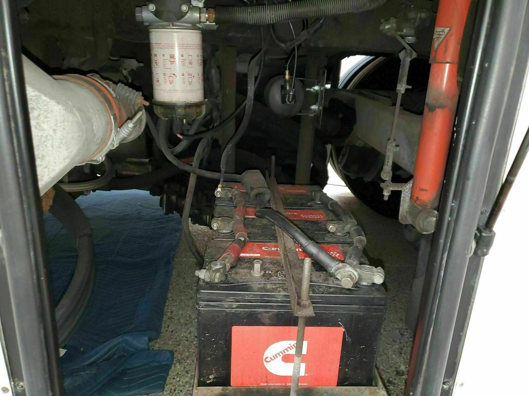
We had many issues to address in our starting battery compartment. The primary thing we wanted to address were the slow starting of the engine, often requiring the use of the boost switch to prevent setting the engine light due to low volage at the ECM (set during cranking).
In addition to that, there were a host of other issues. An updated fuel filter was installed where the OEM was, but due to its size it ended up to close to the CAC inlet. The added ping tank for the toad supplemental braking was not secured and dressed as well as it could be. There was no battery disconnect switch. Overall cable dressing and management.
Items we want to address
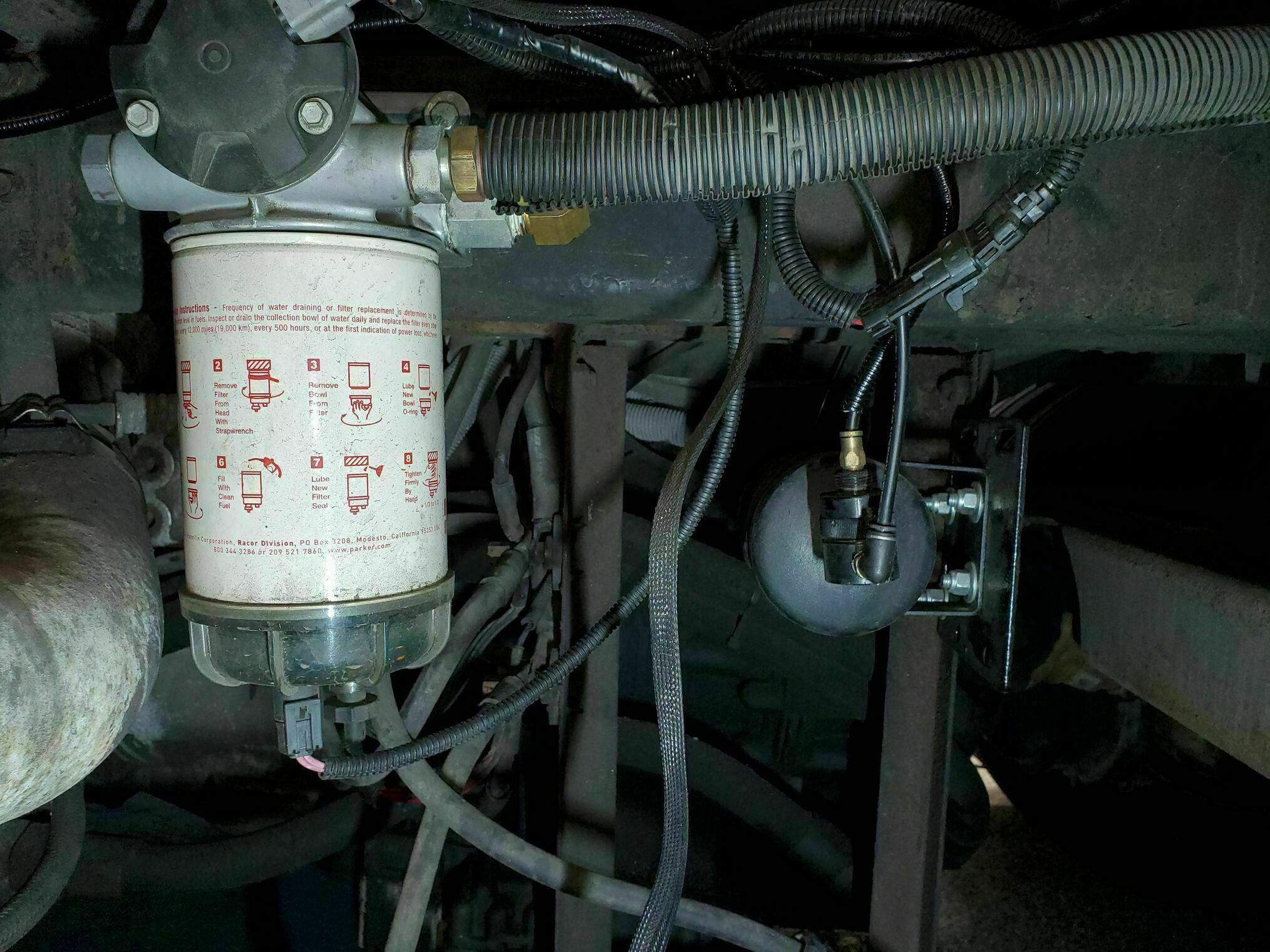
- Proximity of fuel filter to the CAC inlet pipe. When the filter was updated it ended up closer to the CAC than the original (due to its size/length). I want to move it down the frame rail to increase the clearance and reduce the heating from the CAC inlet.
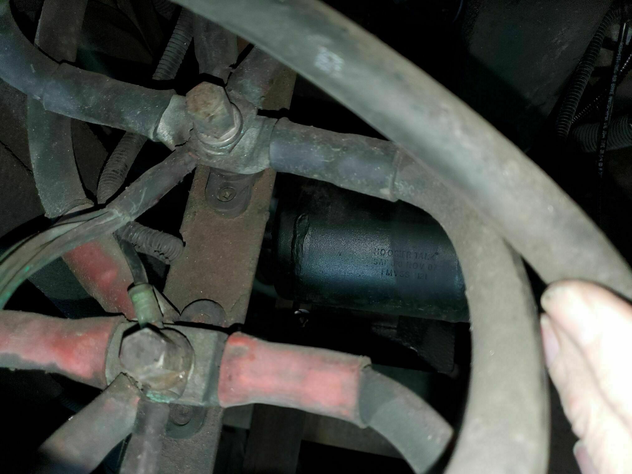
- The air force one Ping tank is mounted transverse and is in an area I want to add some updates, so that needs to move.
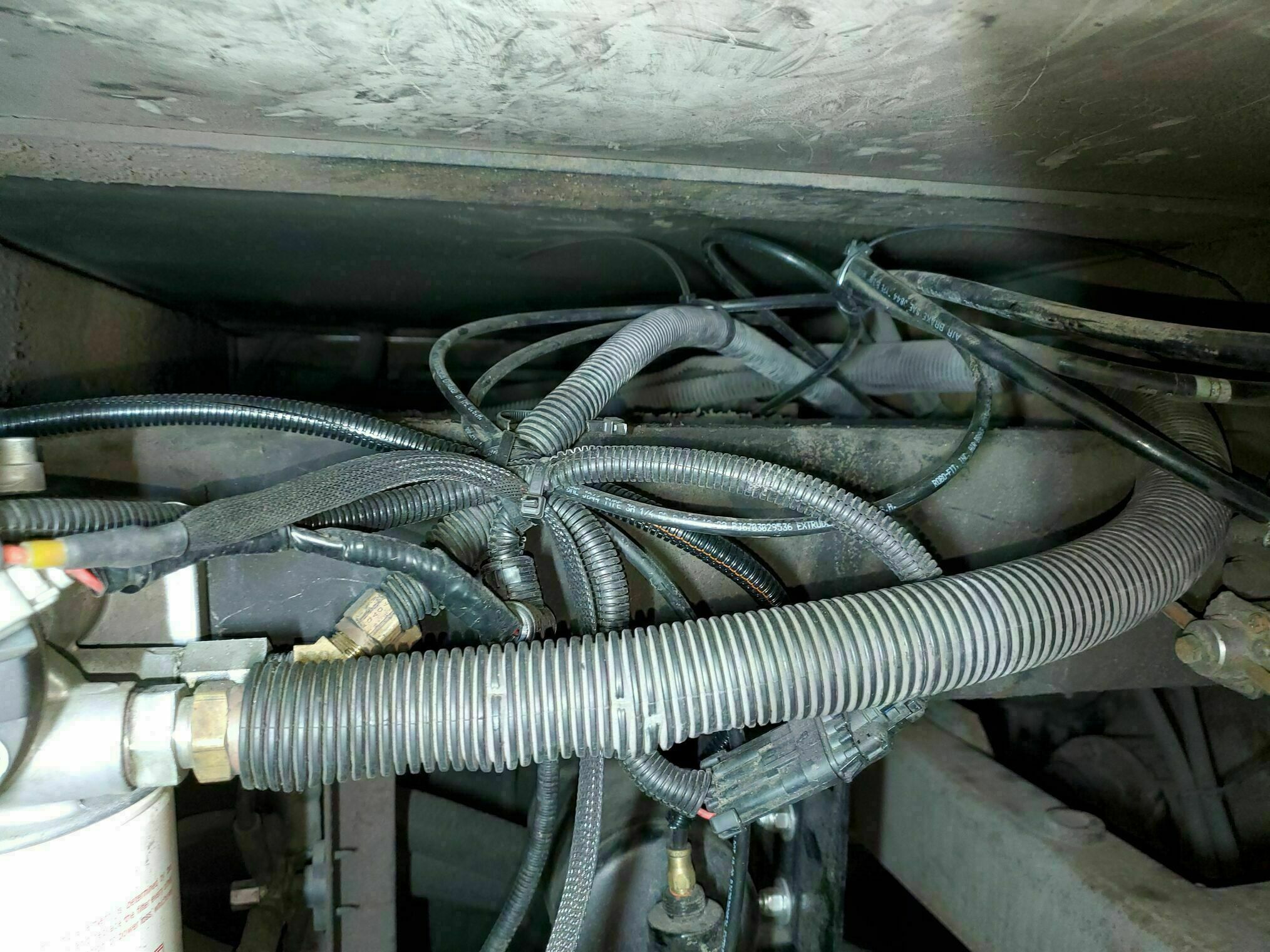
- A lot of the wiring / air lines routing/securing is not great.
- S L O W cranking on the starter. The engine will start but often sets the check engine light due to low voltage (code 251 / Power Supply / Invalid Data) to the ECM. Using the boost does prevent that, but that should not be needed. Improving the battery cabling is a must.
Identify Problems and Opportunities
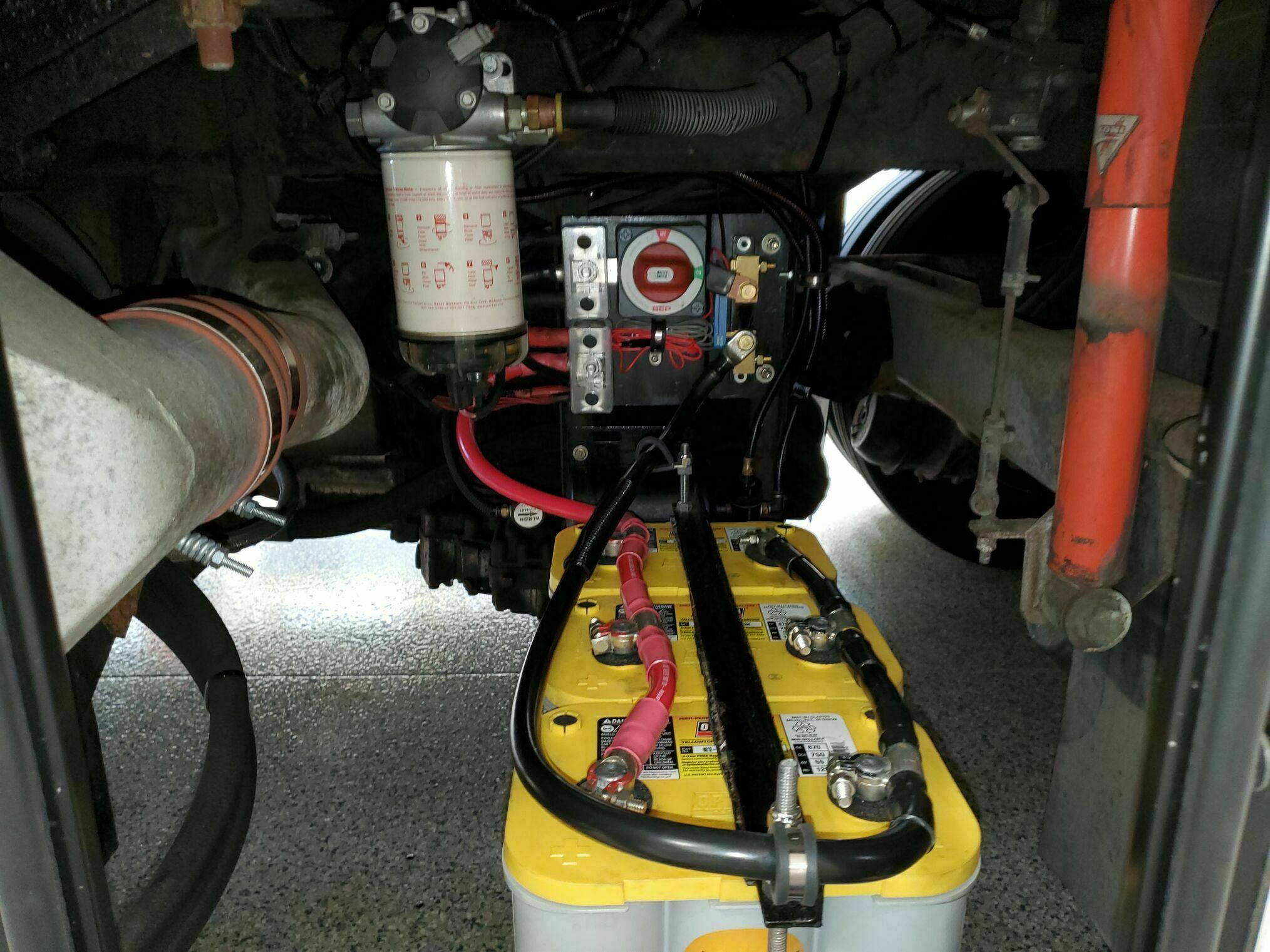
Looking at the existing battery cabling, all the connections terminate on (2) frame mounted single point power posts. In the picture the negative post is on top and positive one at the bottom. (5) cables go to each of the posts but there are only (4) lugs as one of them is a pass though / union lug.
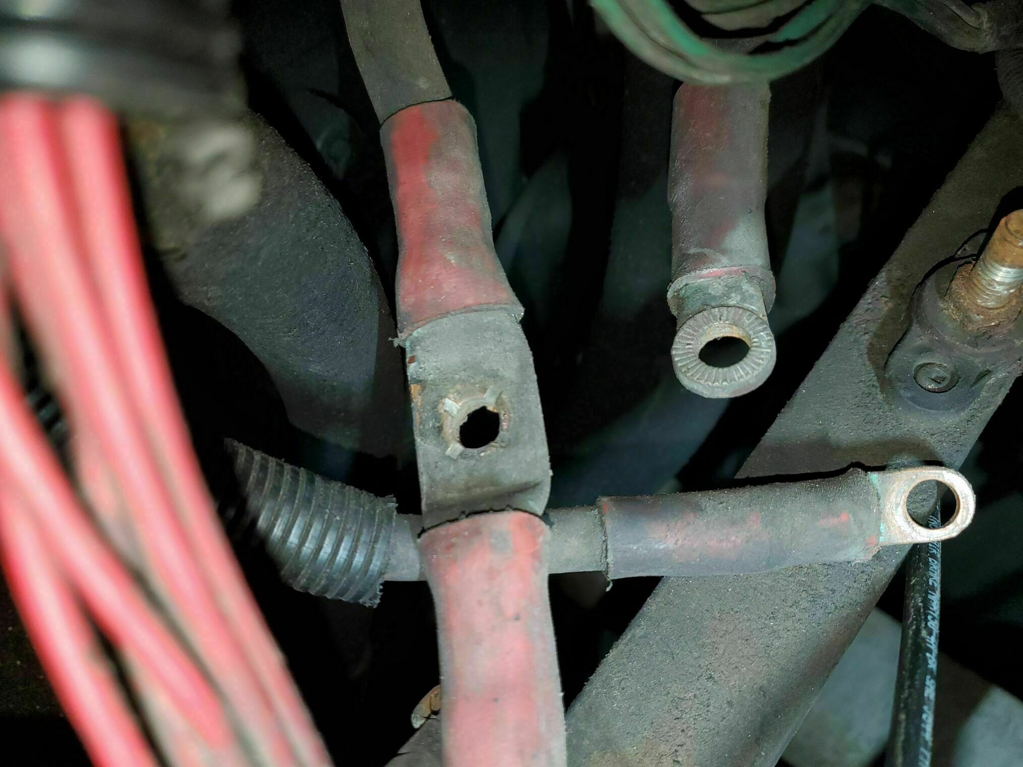
The first lug has serrated/locking faces which have no corresponding/matching mating surface. As such all it accomplishes is to reduce the contact area. That line starts from one side of the boost solenoid, it allows connection to the alternator and when the boost switch is on, to the coach battery’s.
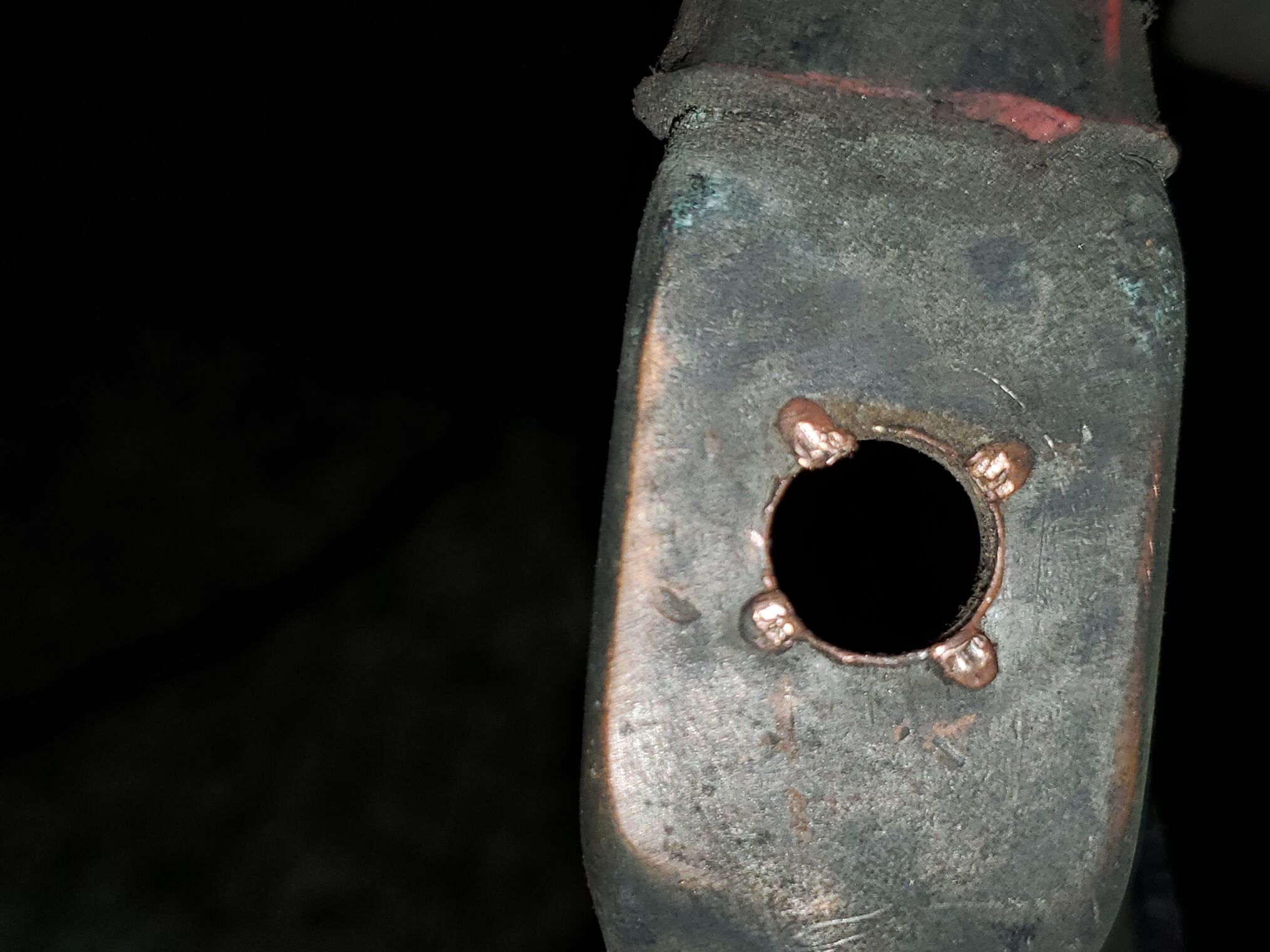
The next lug is the union lug, one side goes directly to the starter and the other to the battery bank. This is good as it allows a direct connection from the starter to the battery bank Looking at the picture you can see (4) indents and (4) protrusions in that union lug face, kind of looks like die press marks. Those 4 protrusions are the part that contact the above serrated lug. This is a poor connection that minimizes the contact area.
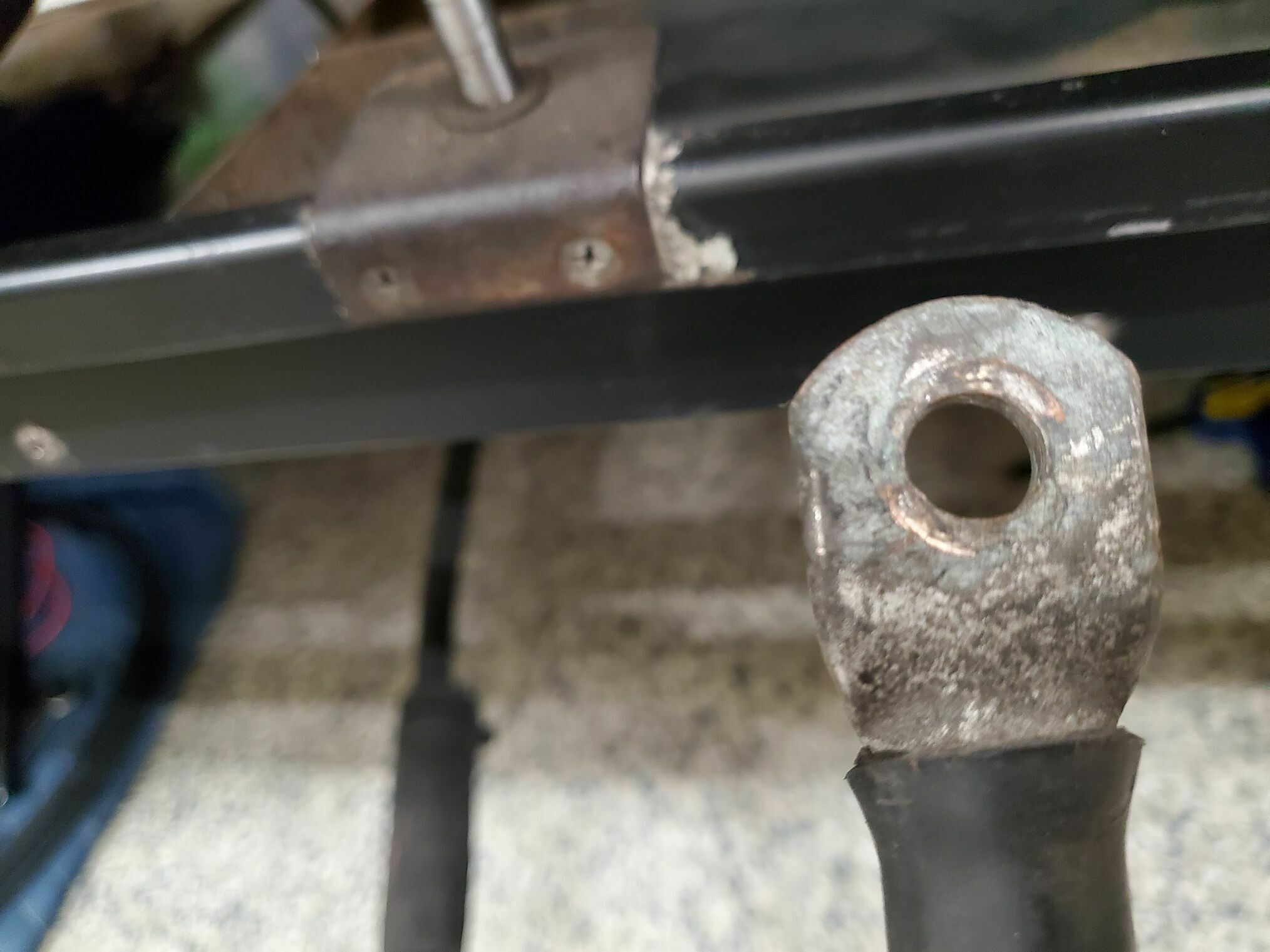
Next is the battery lug (the one from the union cable) where it attaches to the battery bank. The battery bank cable ends in what I would call an accessory post, something that you would attach an accessory to such as a winch. The contact area of the lug to that post is limited, and not acceptable for pulling the 1000+ cranking amps the ISM requires. You can see in the picture how little contact is actually being made to the 3/0 lug.
The next lug on the stack goes to a 90 amp fuse and then on to the front of the coach to the ignition relays and rails. This connection seems fine. The last connection is the one with all the wires, it goes to the ECM and perhaps the 12V panel at the foot of the bed. Again this connection looks fine.
Updates
To improve the fuel filter location, I drilled and tapped new holes, so I could shift it down the frame rail. It ended up just being a couple of inches, but the clearance is much better. I did not measure, but those frame rails must be a 1/4” thick, so have a good cobalt drill bit and use a drop or two of cutting fluid like Tap Magic. I tapped them with a 5/16”-18 tap (drilled a 17/64” pilot hole), again using Tap Magic and going slow; the last thing you want to do is snap a tap.
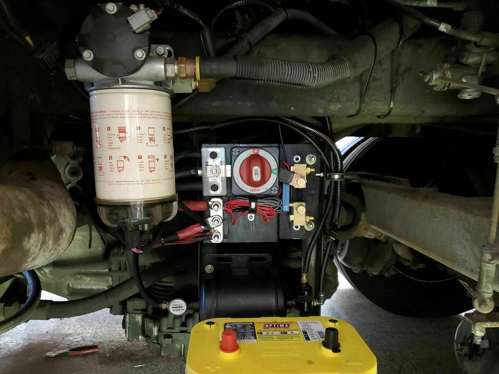
The ping tank was moved down and rotated 90 degrees. I added a metal plate below it for some added protection. The air lines were rerouted and placed in split loom and cable guides. There was quite a bit of excess, so I was able to remove several feet from the length once they had been rerouted.
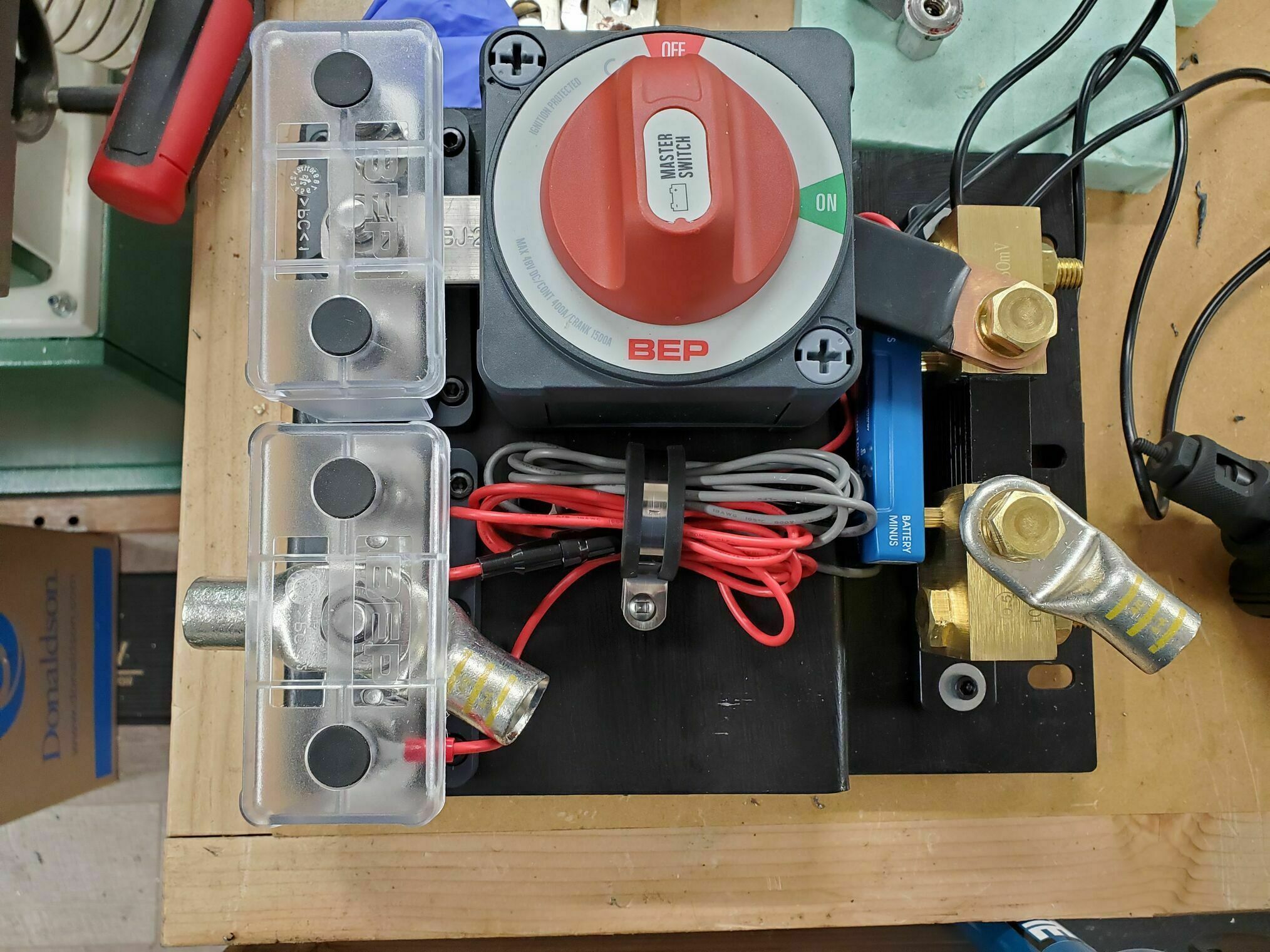
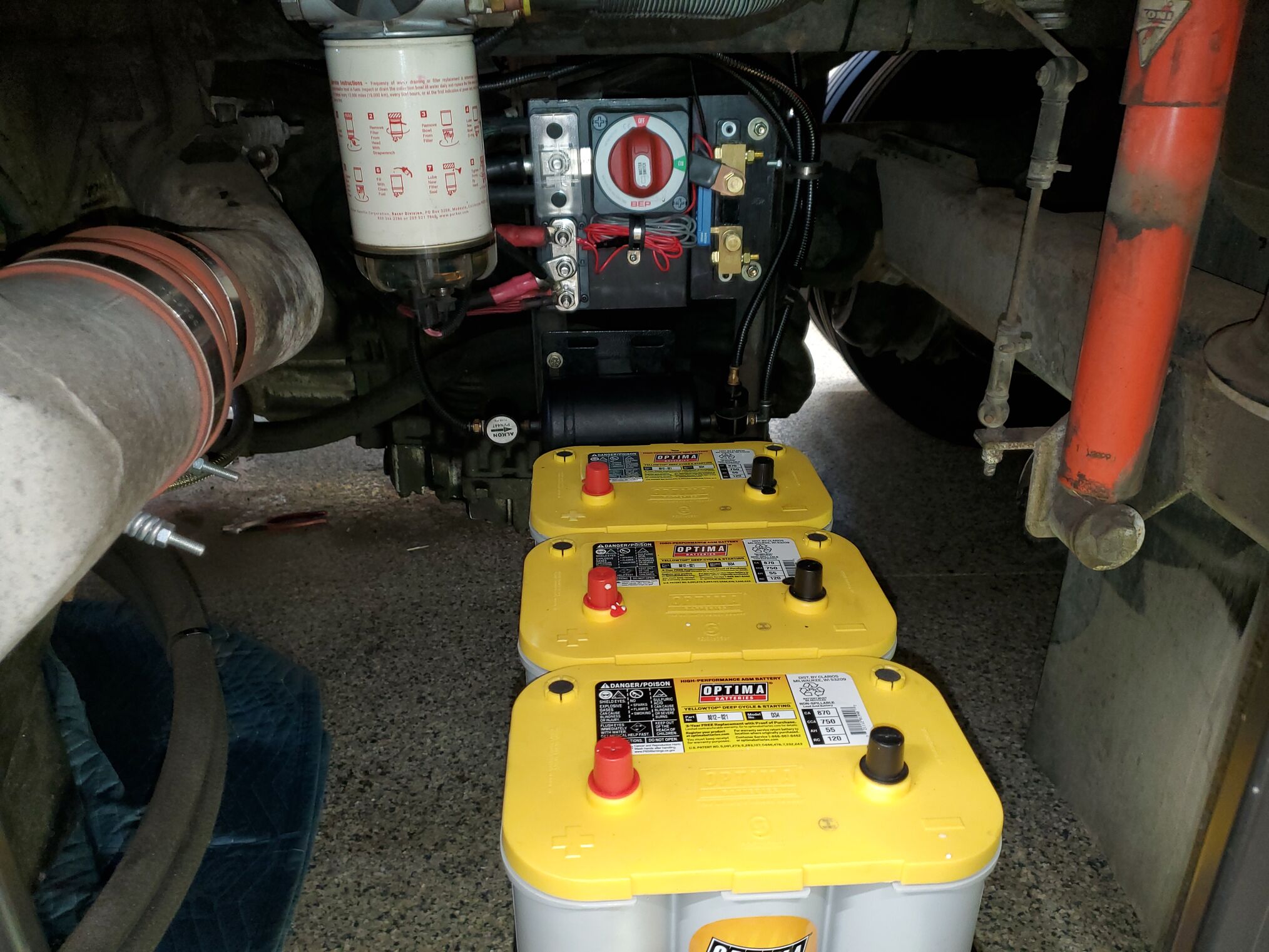
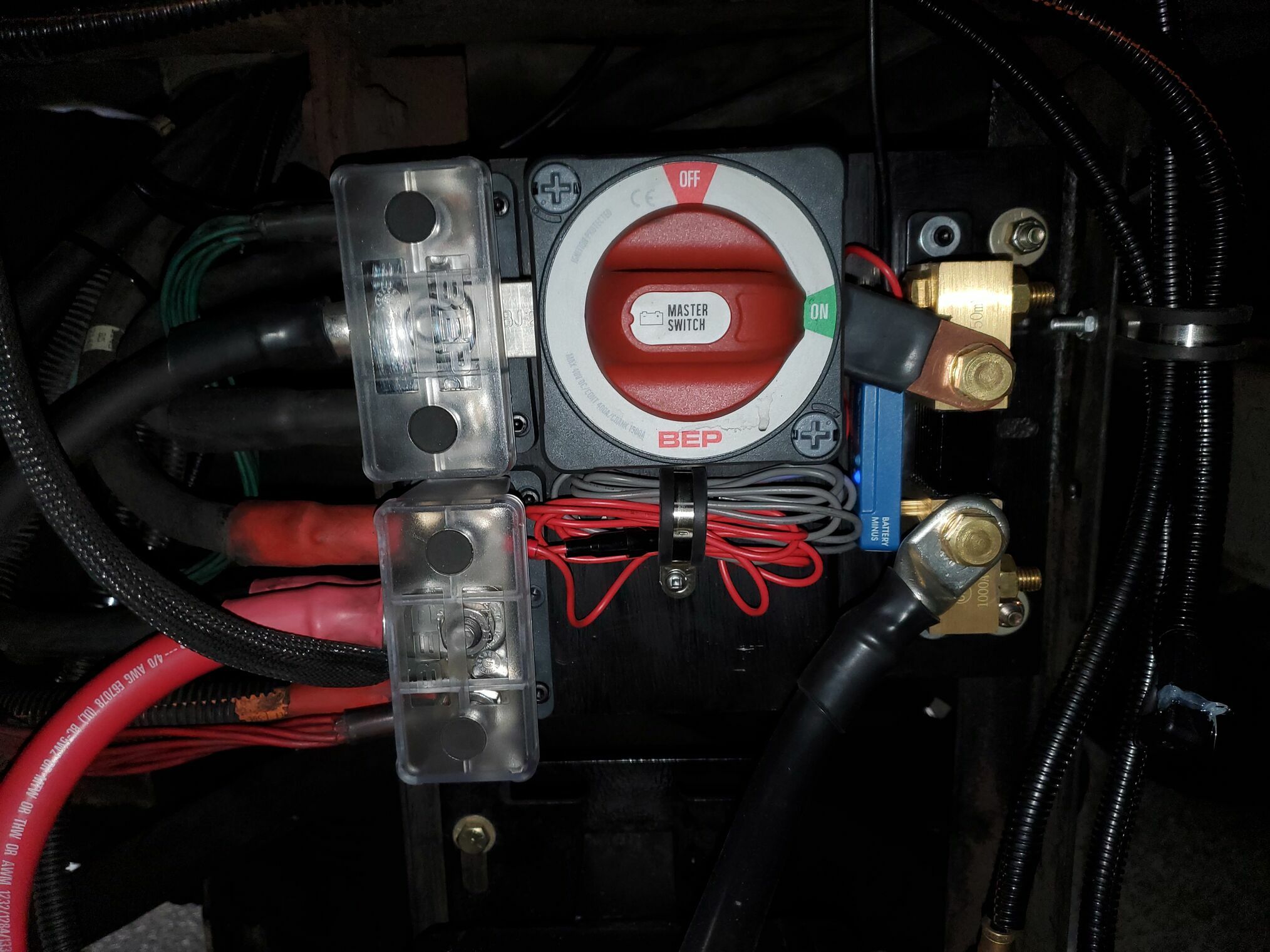
Added a mounting panel that holds buss bars, shutoff, and shunt. Those components are connected together with double copper bars for plenty of capacity. The panel has a step that helps to keep the various connections on-plane. The items used on the panel are:
- BEP multipoint buss bar to replace the original single-point power posts: BEP 650A 3 Stud Buss Bar
- BEP battery disconnect switch: BEP Pro Installer EZ-Mount On/Off
- Victron IP65 smart shunt, which connects to our Victron Cerbo via a ve.direct cable. Used the 1000-amp version based on discussions with Victron: Victron SmartShunt IP65 1000A Battery Monitor This allows us to monitor the battery status
Modified the pass-thru battery/starter cable to a standard lug end cable that connects the starter to the new buss bar. There was enough existing cable (3/0) to allow me to cut off the existing union lug and compress on a new FTZ Power lug: Tinned power lug battery Did this on both the +/- leads, there was enough slack and space that I could do this without disconnecting the cables from the starter.
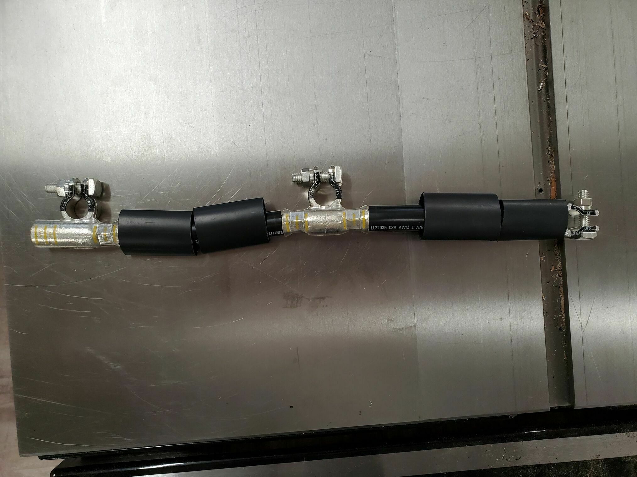
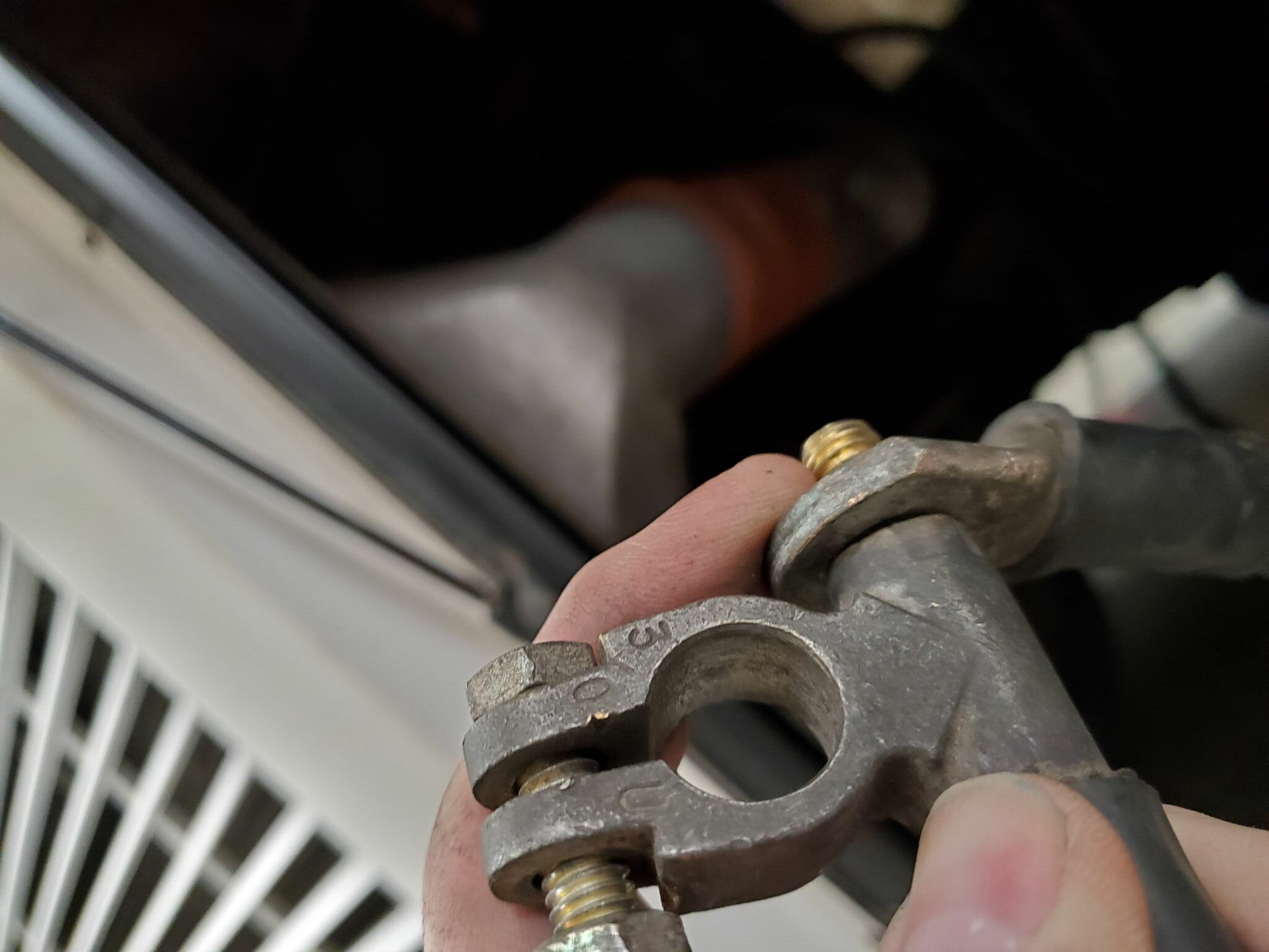
Replaced the battery cables with new marine grade (tinned copper) cable (4/0) that end in a FTZ Power lug (not an accessory post). This lug and the above starter lug are located in the same center (and the only things) buss bar post. I considered using top post (military spec) battery terminals but could not find ones that I felt worked well with the 4/0 cable & the FTZ power lugs.
Added a rubber strip under the battery hold down to provide some compliance and protect the new batteries.
The new buss bars are at the approx height as the original single points but turned 90 degrees. There was enough existing cable to reach the new location, but I would not move those points too far from where they were unless you want to run a new cable. The cables with the serrations / interlocks had the least slack (they connect back to the house batteries), so I could not replace those lugs. Instead, I sanded the serrations down a bit to increase the contact area on the flat surface of the buss bar.
Engine batteries were replaced with Optima Yellow Tops. I remained with the simple / effective diagonally connected arrangement as seen in the photo. It is not the “perfect” setup as there can be slight differences in individual battery currents. Using a single cable, I had to stay with 4/0 for each joint. In the future, I’m considering going to an equal length cable / buss bar arrangement, then I could run 2/0 from each battery to the buss bar and 4/0 from there to the main connections. Downside to that is, you have to deal with more, longer cables and additional buss connections.
Result
With everything in place, we have the most robust starting since we purchased this project. I feel the main issue was the battery cables and the use of the battery accessory post connection adding too much resistance. The Victron monitoring via the Cerbo GX is a very nice addition, as is the ability to have a disconnect switch.