SeeLevel Tank Monitor
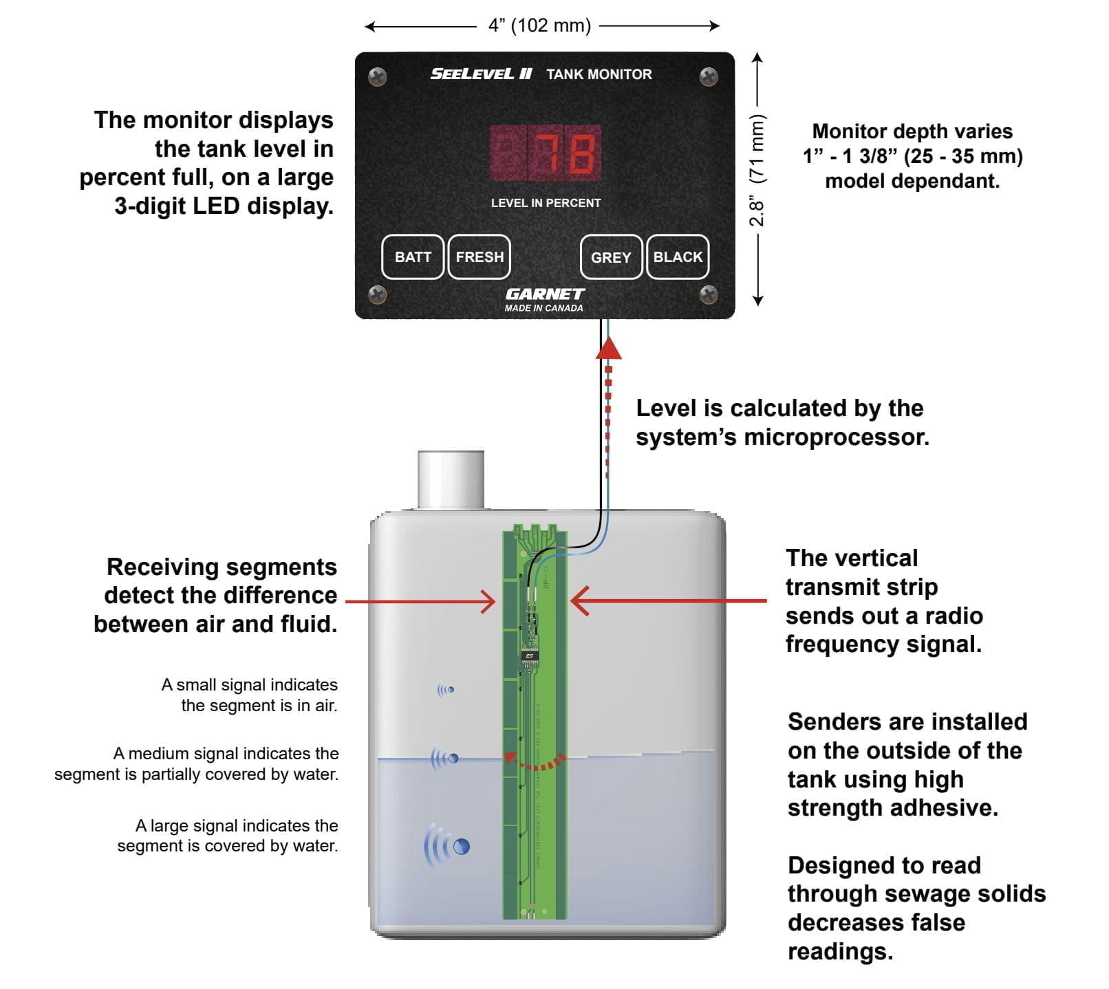
We replaced our Javelina tank monitor with a SeeLevel system. We learned a few things along the way and wanted to write them down for others.
On our 36’ 2900 non-slide, the tanks are very accessible from the Manabloc/water pump bay. Just remove the carpeted wall panel, and you will have excellent access to the flat side of all (3) tanks.
Our plan was to add the SeeLevel display in the utility bay and then use our Victron Cerbo GX MK2 for the inside display. For this to work we went with the N2K (NMEA2000 version) of the SeeLevel 709-N2K-NLP. There are RV-C versions that can work with the Cerbo GX but they have been known to prevent anything else from working on the VE.Can bus.
You will need to make your own CAN data cable, which will plug into the back of the SeeLevel display and the other end into an open/available VE.Can port on the Cerbo GX. For the cable you will need a standard UTP/network cable, a 120 Ohm resistor (1/4W/5%), 3M 37104 4-pin connector. There are plenty of tutorials on how to make this cable, here is a video that explains the steps
Prep and Install
We ran a “smurf” tube (non split loom tubing) across the top of the gray tank and ran the sensor wires inside to get from side to side. The tubing will make it easy for any future side to side wiring runs. Next We cleaned the tank faces, first with Simple Green and then denatured alcohol. The instructions recommend temporally positioning the sensors with painter’s tape. I assure you, that will not adhere to the (polyethylene) tanks. In fact, I think it repels. I then tried regular duct tape, not industrial/Gorilla, but plain old duct tape. That weakly adhered to the tanks but did stick well to the sensor faces. Doing a lite sanding on the tank faces with a green scouring pad greatly improved the duct tape adhesion. I could not really see a change on the tank faces pre/post scrubbing, but it must have raised enough grain for the tape to grab.
With the sensors stacked, positioned and temporally held in place plus all temporary wiring in place, we hooked up the display in the wet bay. The display blinked values (see video) when you pressed battery/grey/etc but did not stay on. A really strange behavior. We contacted Garnet and after some diagnostic steps, they felt it was a bad display. We waited until a new one arrived and, you guessed it, got the same behavior.
I took the display and powered it with a DC 12v power supply and it ran fine. I tried another source of 12V, the one going to the bay lights, and the unit also worked fine. I had originally spliced off the 12V line that goes to the water pump / fill switches, the ones used to signal those relays to activate. The digital voltmeter read 13.8V on that line, so I can only assume it’s fed from a capacitor or provides a low current (dry) current. The display circuit would drain and then slowly recharge, causing the pulsing.
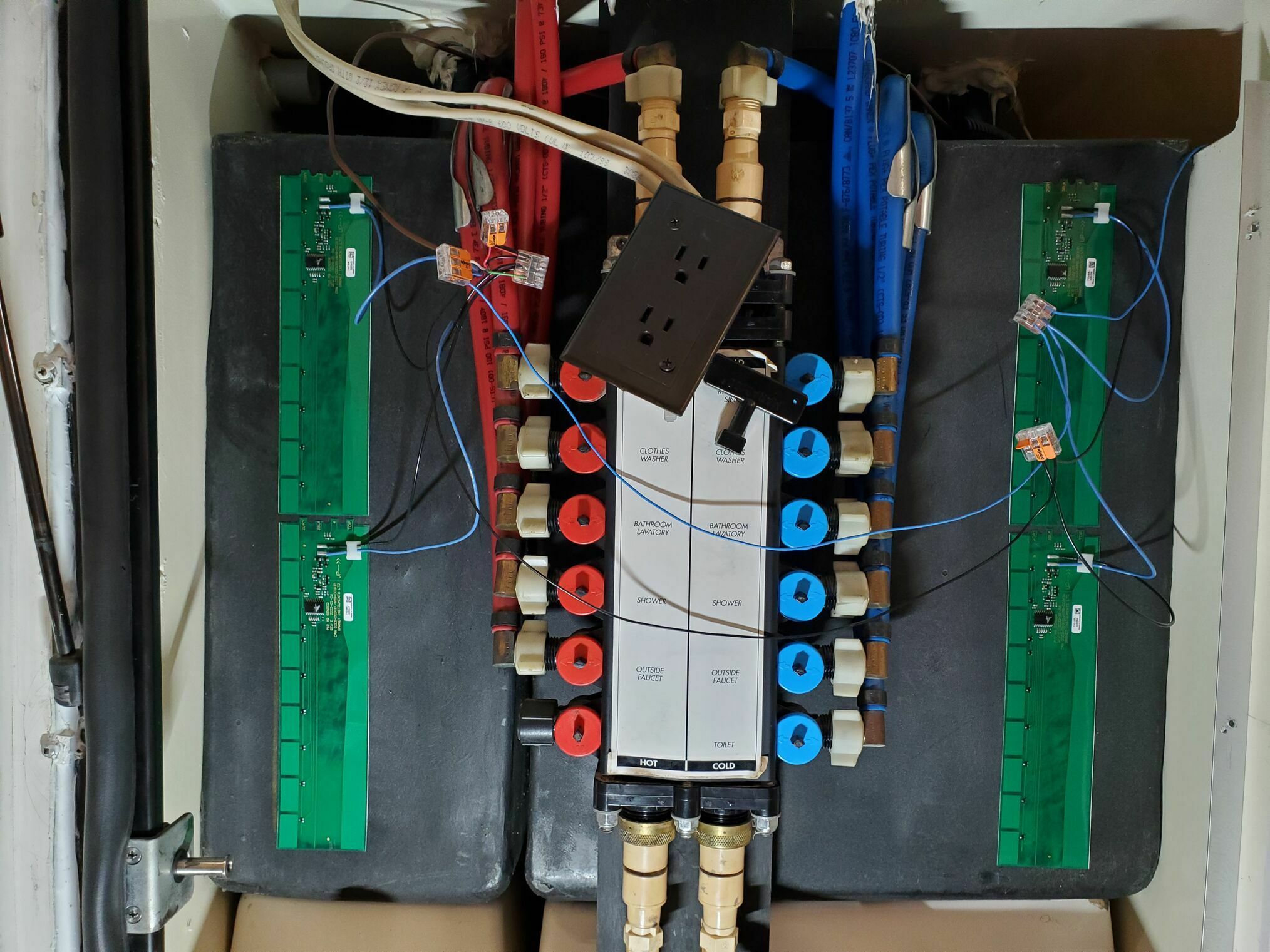
With the voltage oddities understood, I redid all the temporary sensor placements. As part of debugging the display issue, I had removed everything, sensors, tape and wiring, to make sure none of that was causing the problem. With Everything back things were working and reading as they should.
Problems solved?
With the voltage problem solved, the final installation. I removed the 3M liner from the back of the sensors and aligned them to the marks I had made during the temporary positioning. That 3M adhesive will stick tenaciously to the tank, so only expose enough to get it aligned to your marks and then peel as you go. All the wires were then put in split looms and Gorilla tape was on the top/bottom of the sensors as insurance. Once complete, gave it a test, and the system showed random readings, like black and grey tanks at 30 to 40 percent.
Sigh … One by one, I UN-wired the sensors to see if I had broken one during the installation. I removed the split loom, I removed the Gorilla tape, then suddenly it was reading normally, ARGH. Fine, I’ll redo this again another day.
The saga continues
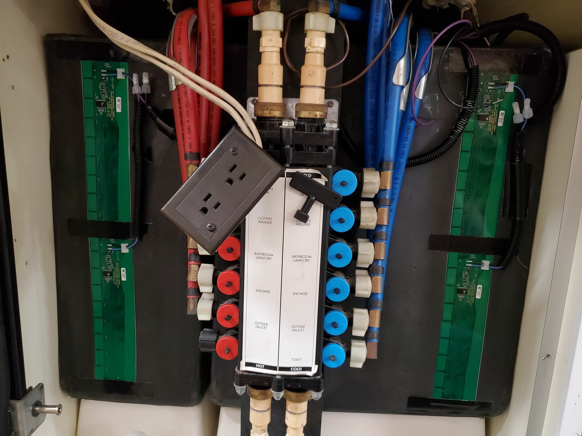
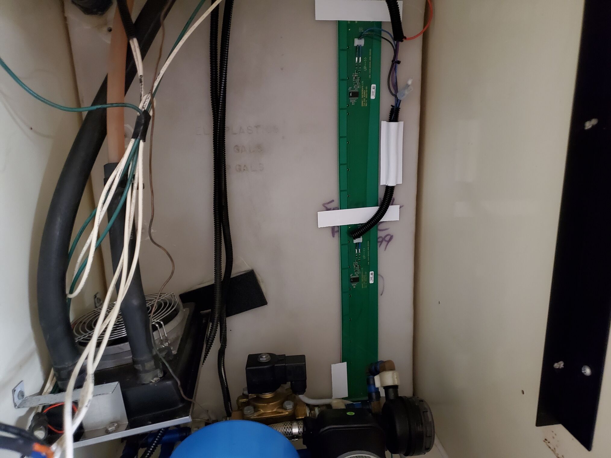
The “another day” came, and I re-wired up the black tank, split loom, tape, etc. Did a test, all good. Then the grey tank and testing was all good. Next, the fresh tank, gave it a test and now ALL the sensors reported ERR. At this point I’m thinking that old Javelina system is looking pretty sweet. In looking into the ERR readouts, the only thing mentioned was to check for any electrical/EMI interference. I decided to power it (again) with a regulated DC 12v power supply and it (again) ran fine. Back on coach 12V, and it output all ERR, so a dirty/bad power/ground was confusing the SeeLevel.
We remembered an electrical issue on our 2003 with the fluorescent lights and decided to go on a coach lights on/off check. We found that if the front Thin-Lite fluorescent was on, the SeeLevel would display ERR on all tank values. If it was off and other lights were on, it would act normally. If it was on and others were on, you may get an abnormal reading or ERR. Old ballast = bad SeeLevel mojo. Throughout the numerous installations, various lights had been on/off depending on what work was being done inside, all of which led to the wonky and seemingly random behavior.
To clamp/prevent the power issues that the fixtures/ballast are causing I added in an automotive power filter basically a LC filter that prevent the noise from getting to the SeeLevel. To add the filter, I simply wired the 12V and ground in to this and the output to the SeeLevel. Eventually I will convert those lights to the LED which will eliminate the ballast noise.
Finished
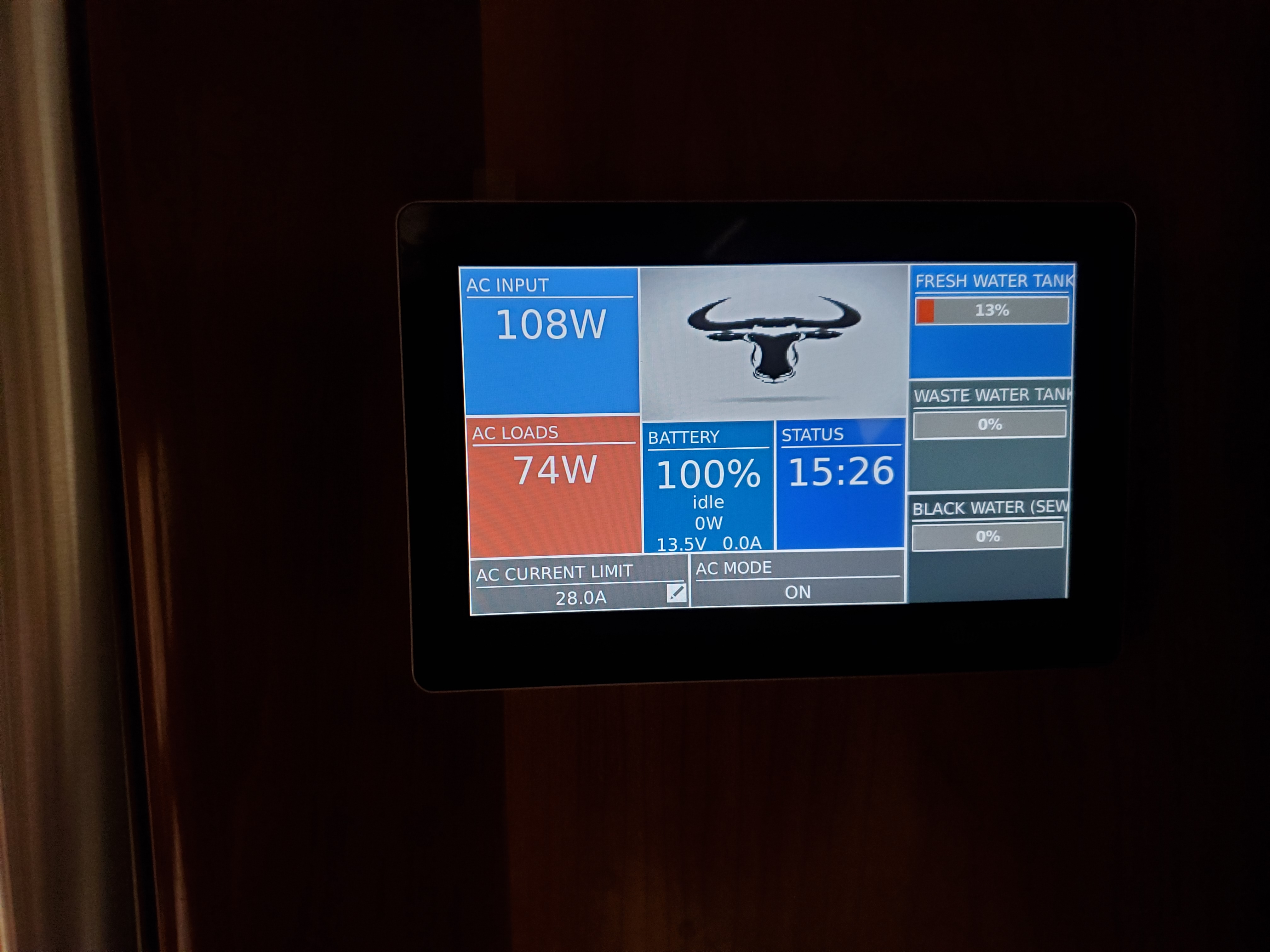
I think I’ve done 4 complete installations of this system, so if anyone needs help or bad luck, give me a call. Just kidding, I dont ever want to do another one! Anyway, a 2-3 hour job turned into a couple of weeks of “fun” but it’s done.


