Victron Multiplus Mounting
With the AC wiring in place, it was time to mount the Multiplus II, PD52V 5200 Transfer Switch, and the 50 Amp EMS/Surge Protector. When adding the AC wiring, we left extra to allow flexibility in mounting — whether on a single wall or split between both.
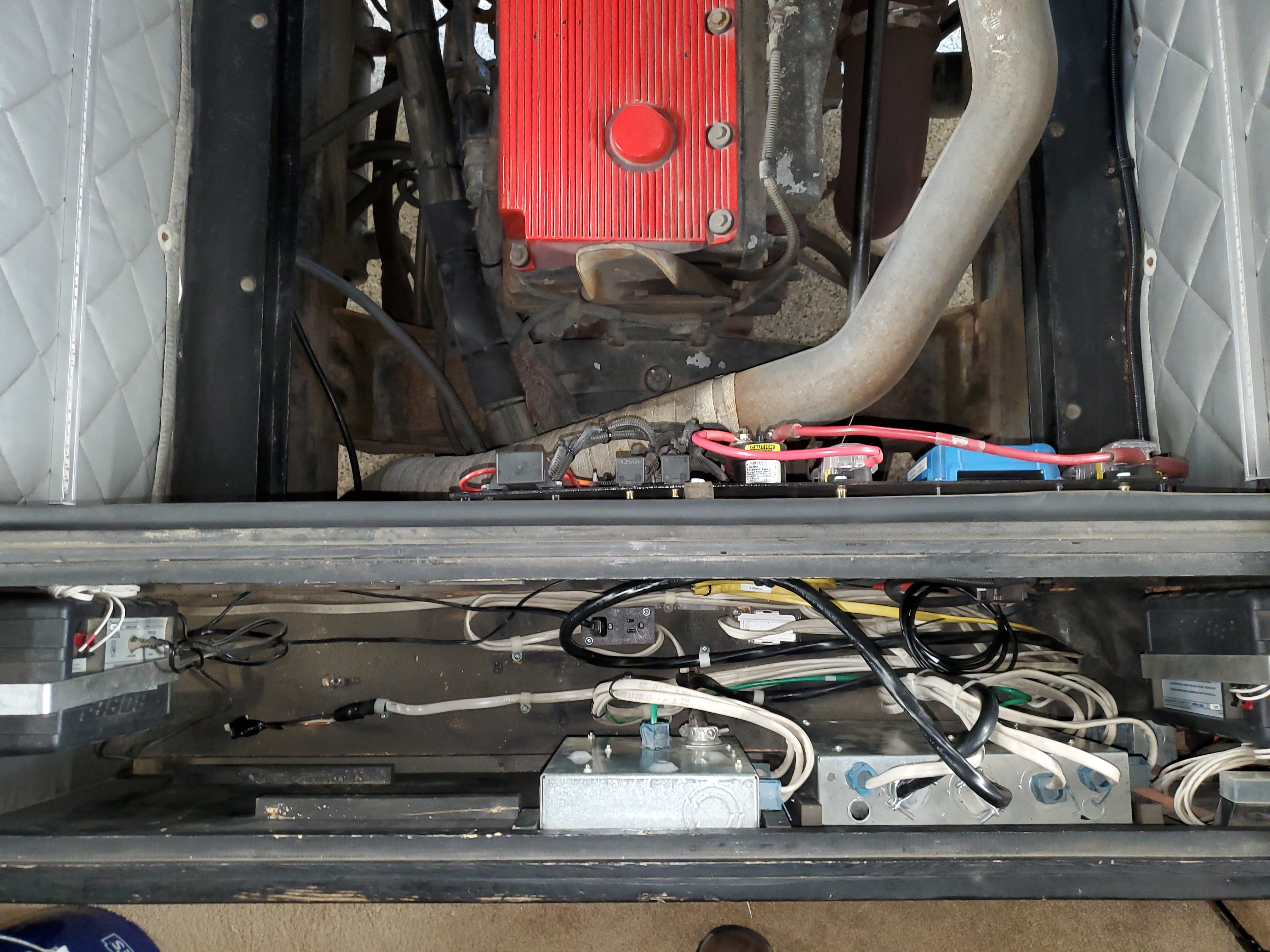
We ultimately chose to mount everything on the rear wall. That wall already hosts several components, such as the HWH Pump, AquaHot overflow, cable cover, and transmission module — so a few more wouldn’t make a difference. This approach also avoided having to route Romex across the bay through an already cramped cable raceway.
Partition Walls
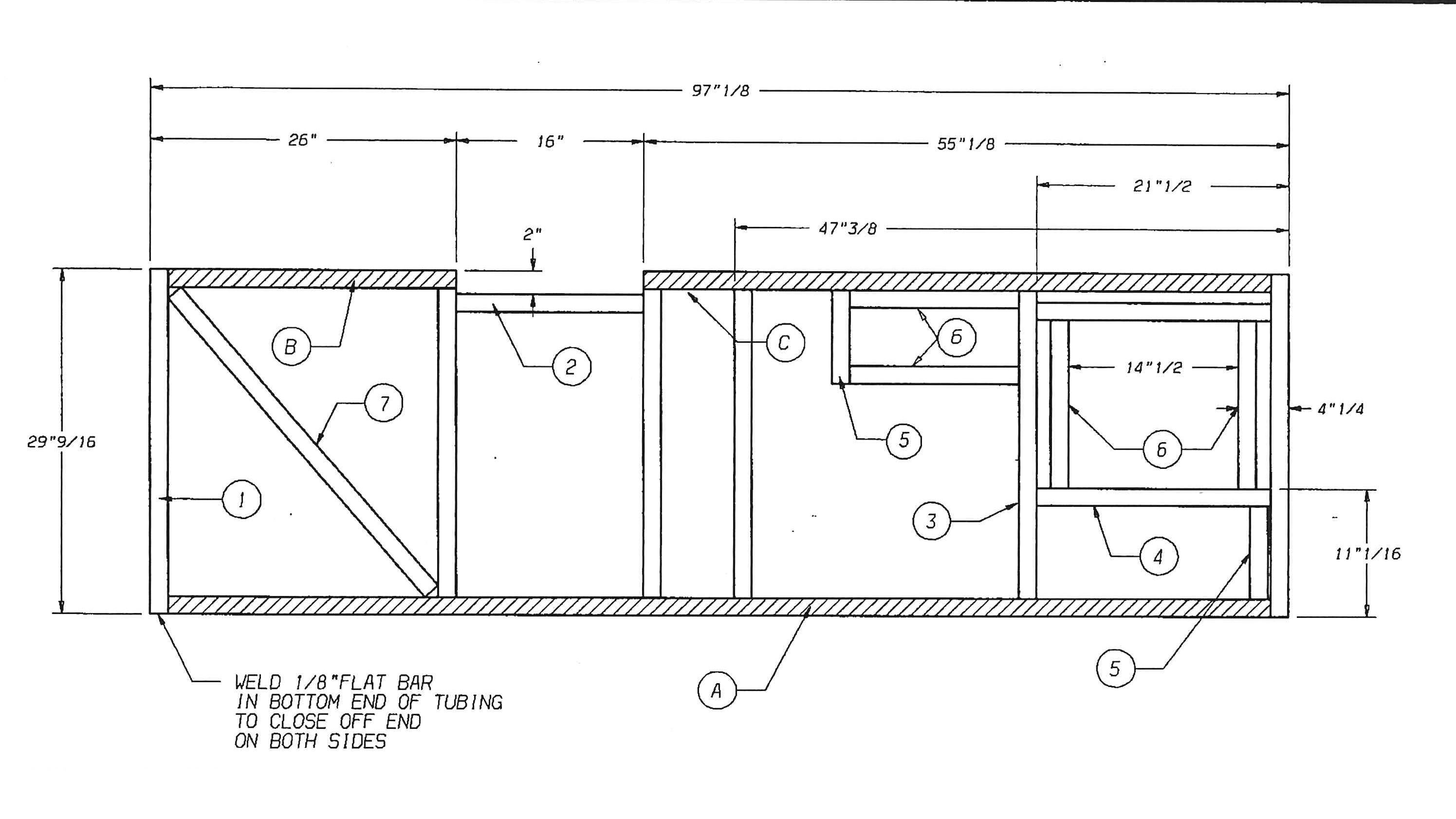
The partition walls are constructed from a framework of welded tube and angle brackets. This structure is then skinned with thin Filon sheeting and finished with a layer of bay carpet.
The specific layout of these beams varies by partition and model year. Use a magnet to locate the steel tubes before drilling — the Filon alone isn’t strong enough to support heavy components, even with rivnuts or similar fasteners.
Transfer Switch and EMS Mounting
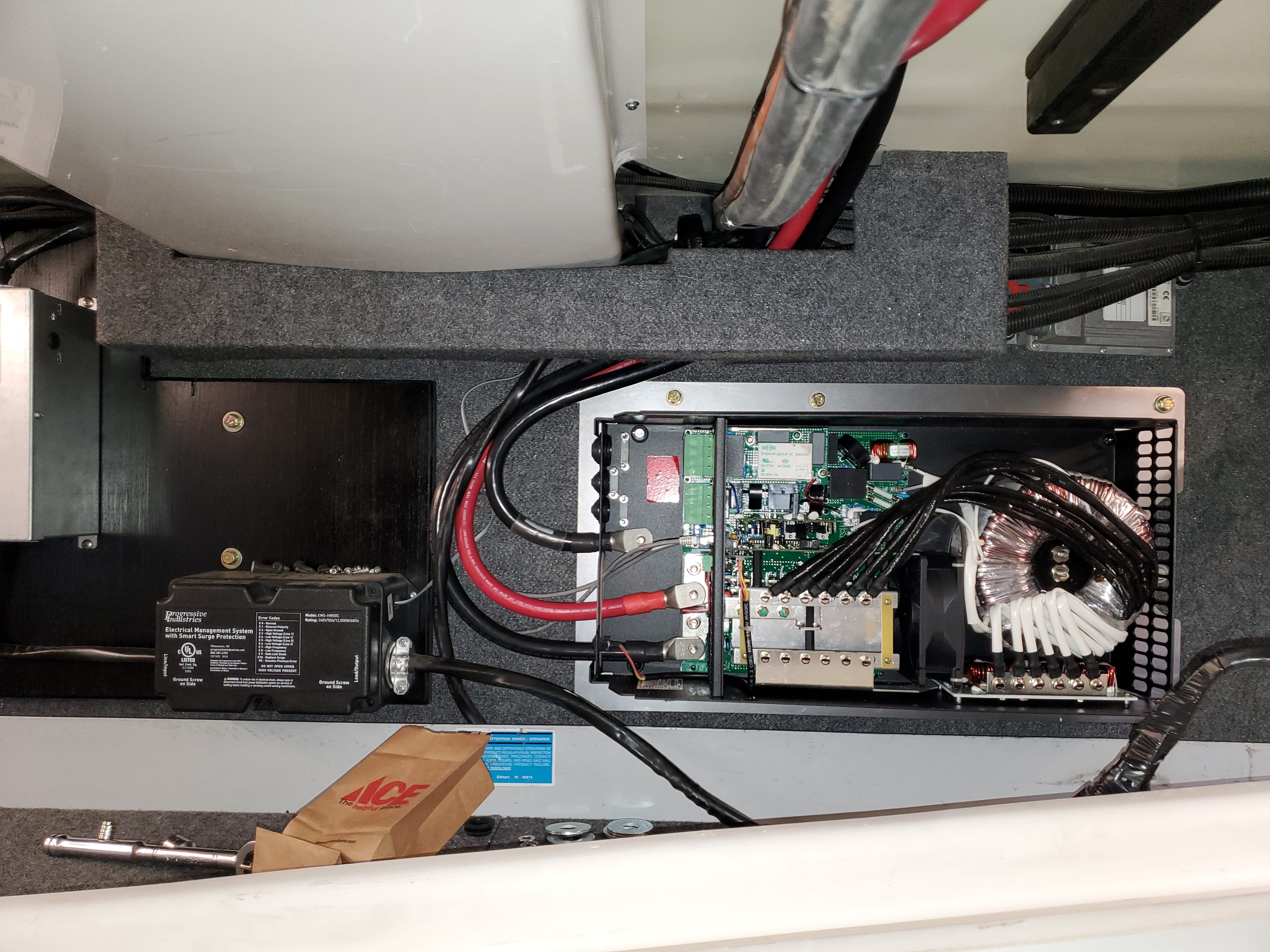
I cut an L-shaped piece of 3/4” plywood to serve as a mounting base for the Progressive Industries 50 Amp RV Surge Protector/EMS and Progressive Dynamics PD52V Automatic Transfer Switch.
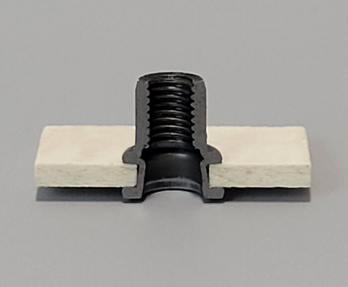
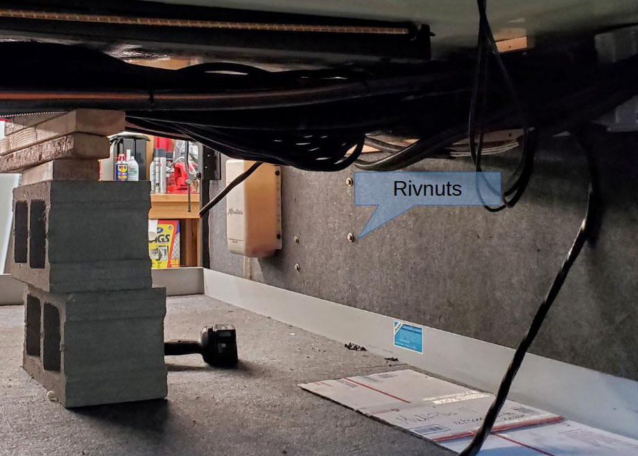
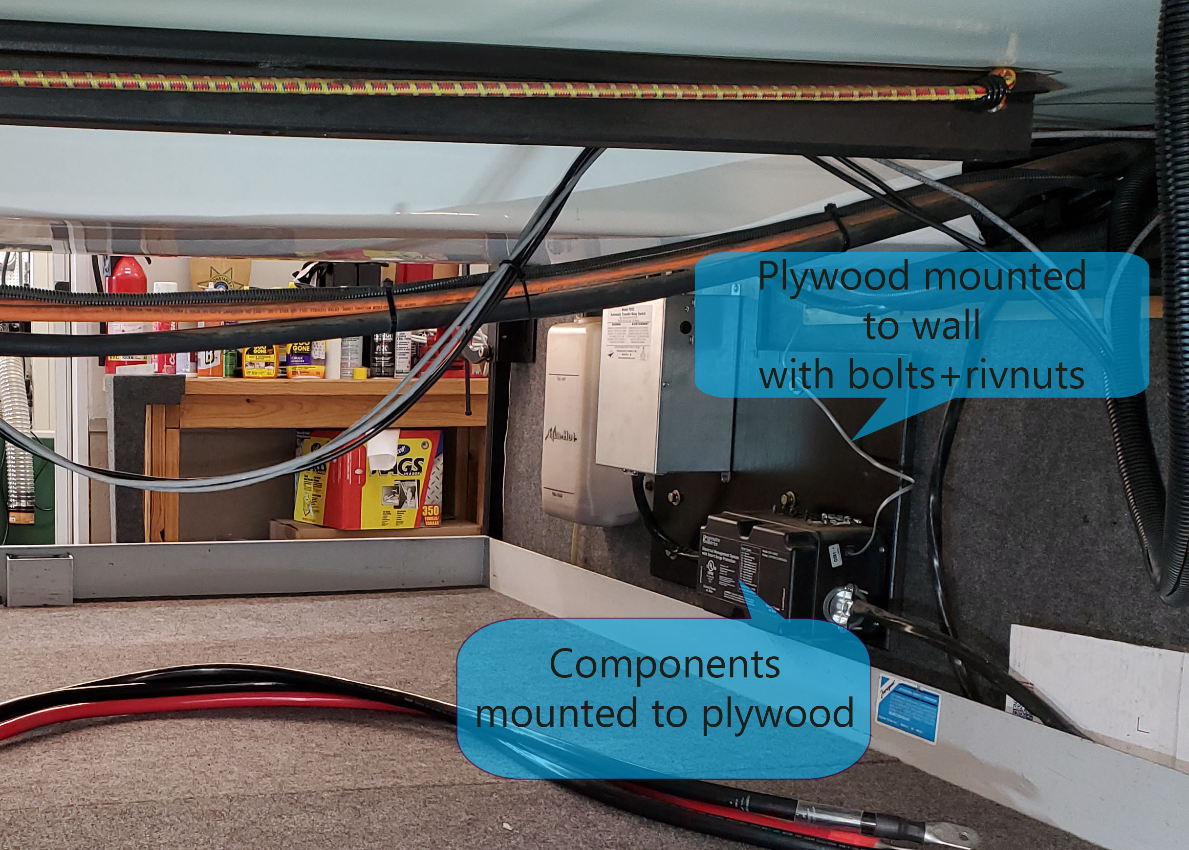
You’re unlikely to find structural steel exactly where you need it, so it’s best to use an intermediate mounting plate. This plate can be anchored to known structural points and then used to mount the equipment. The plywood L-plate was attached to the wall using Rivnuts installed in the steel tubing. The transfer switch and EMS were then secured to the plywood.
Wiring
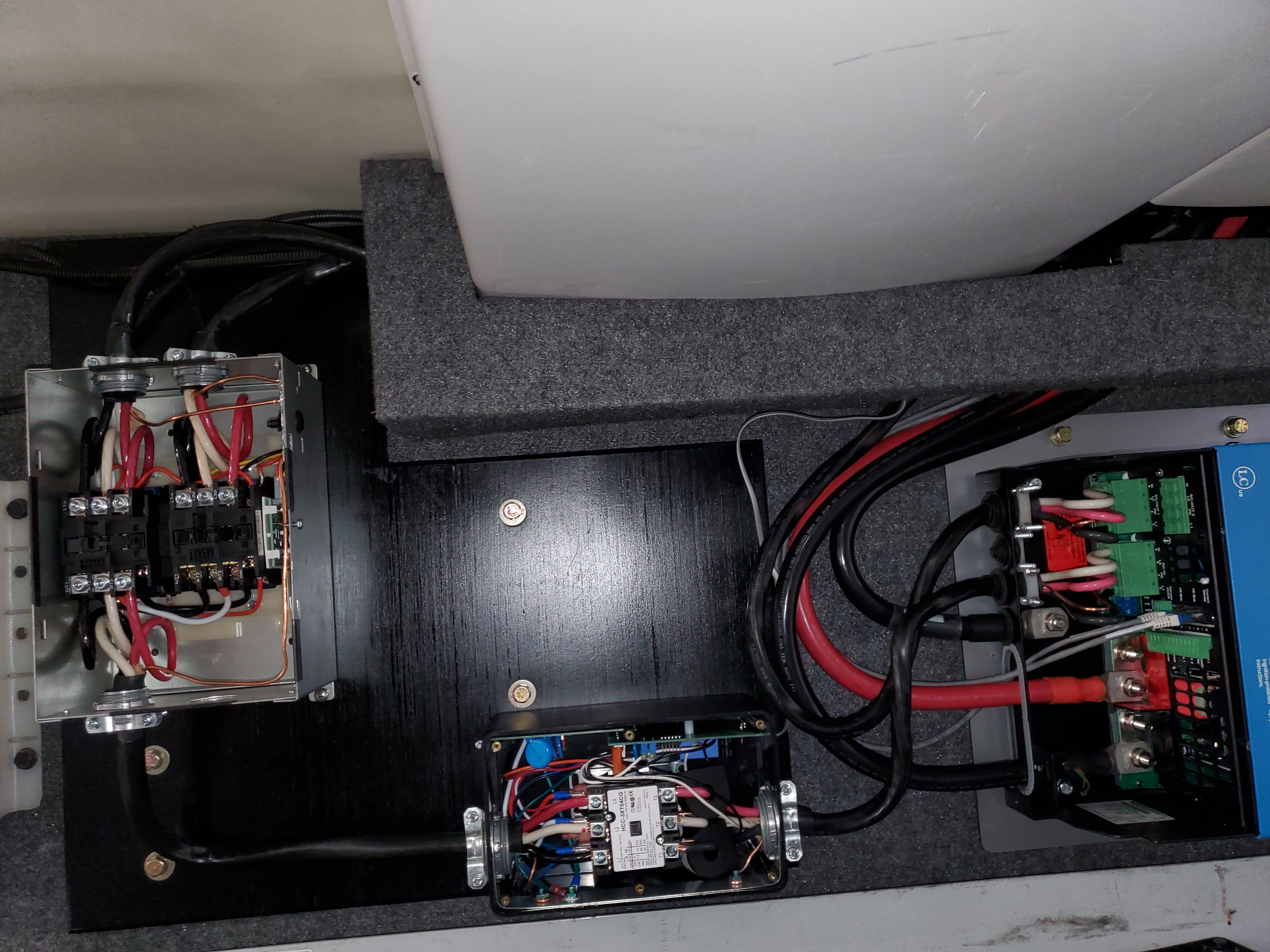
The transfer switch receives input from the 6/3G shore power and 6/3G generator lines, both of which enter at the top. Output from the switch runs through a section of 6/3G to the EMS input. The EMS output then feeds into the AC input of the Multiplus.
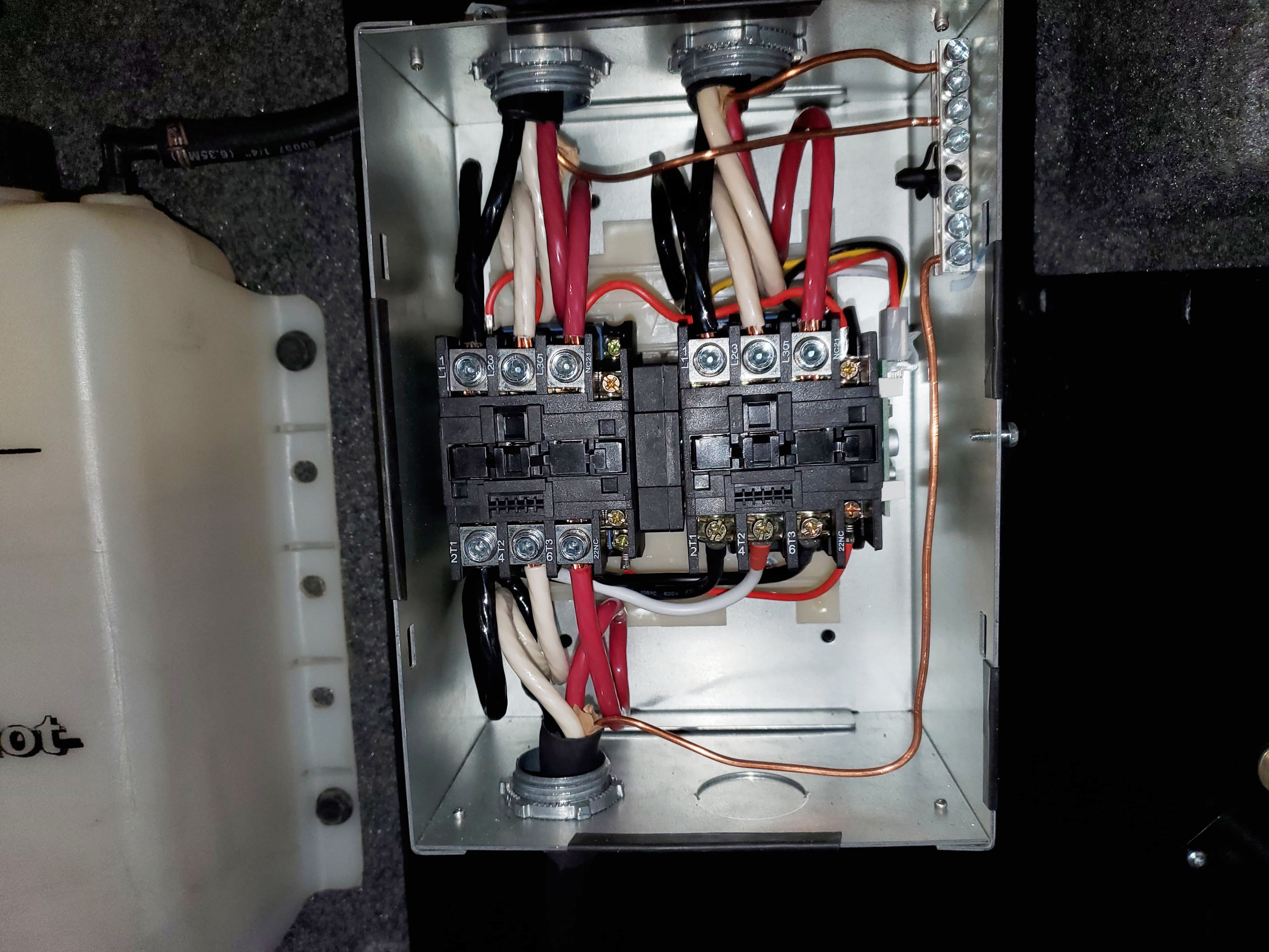
There’s enough space inside the transfer switch box to create small service loops in the Romex. These loops make routing easier and offer flexibility during maintenance or future upgrades.
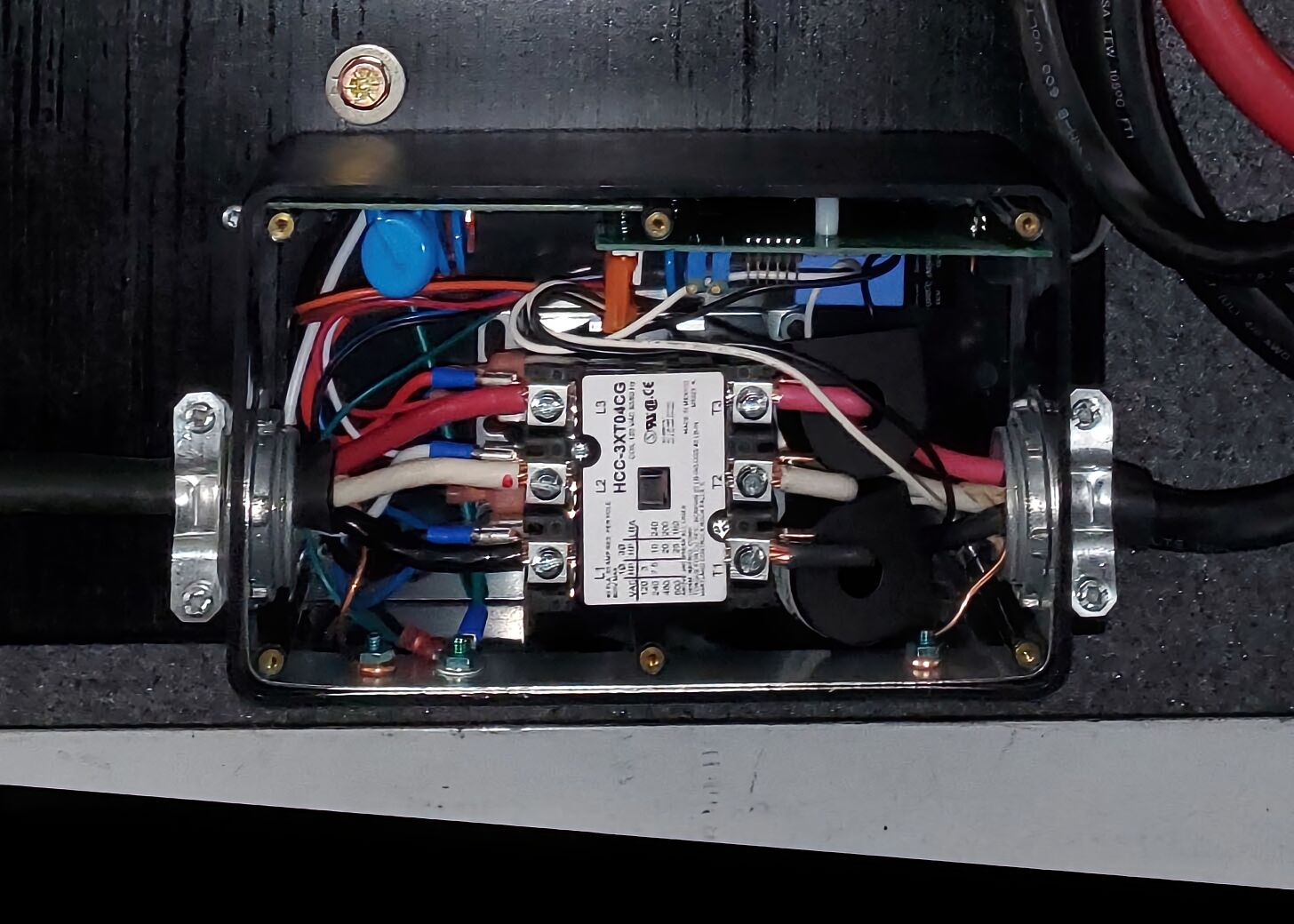
The EMS wiring is tight and not well thought out. The input side leaves no room for slack. The output side is only slightly better, but you still have to fit #6 wire and two current sensor rings into a cramped area. You must also be cautious not to damage the exposed, circuit board during installation. I installed one of these units 20 years ago, and it’s disappointing that the design hasn’t improved. Using SOOW wire could help, but only if both sides connection blocks support it.
Multiplus Mounting
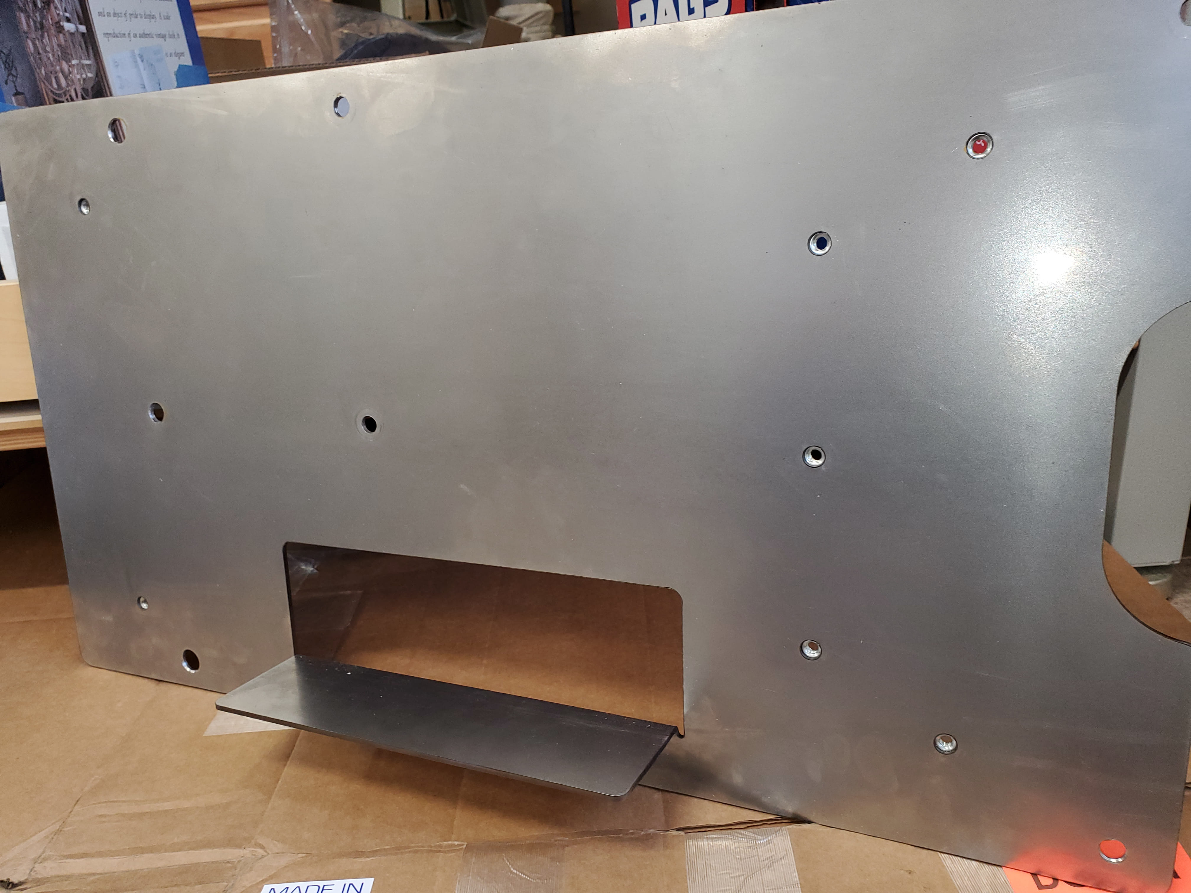
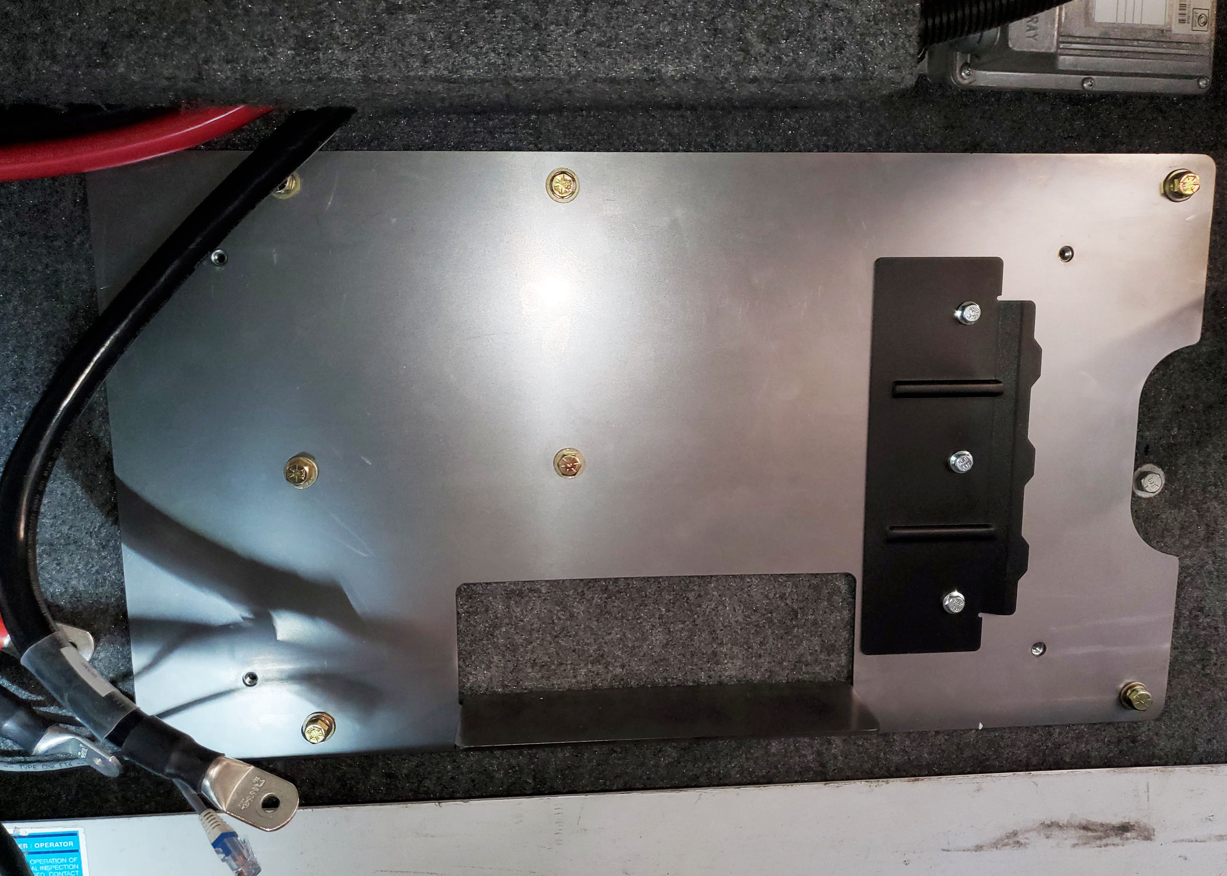
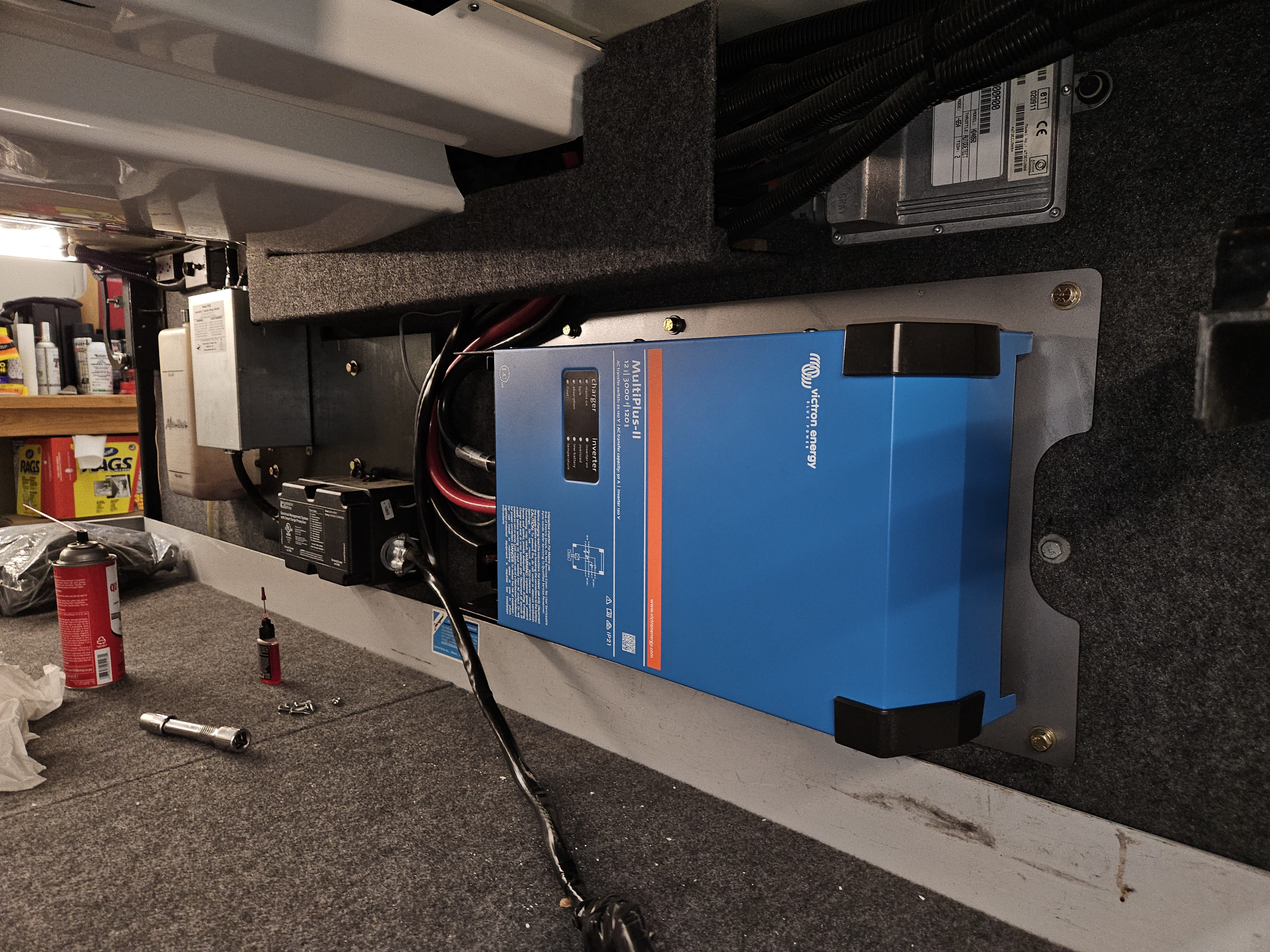
For mounting the Multiplus, we used a steel intermediate plate instead of plywood. This plate was bolted to the wall using Rivnuts and includes press-in nuts at the seven inverter mounting points. The Multiplus weighs in at 66 pounds, and considering the bumps and jolts of the road, a secure installation is critical.
While the unit comes with a vertical mounting bracket, we didn’t have the space for that orientation. Instead, we mounted it horizontally. In this layout, the bracket helps hold the unit flush to the wall but doesn’t bear its weight directly. Fortunately, Victron includes two additional mounting points under the top (blue) cover specifically for horizontal installations.
The plate includes a ledge that supports the inverter during installation. You simply set the Multiplus on the ledge, slide it left to engage the bracket, and then install the four corner bolts with ease — no juggling or awkward alignment required.
DC Wiring
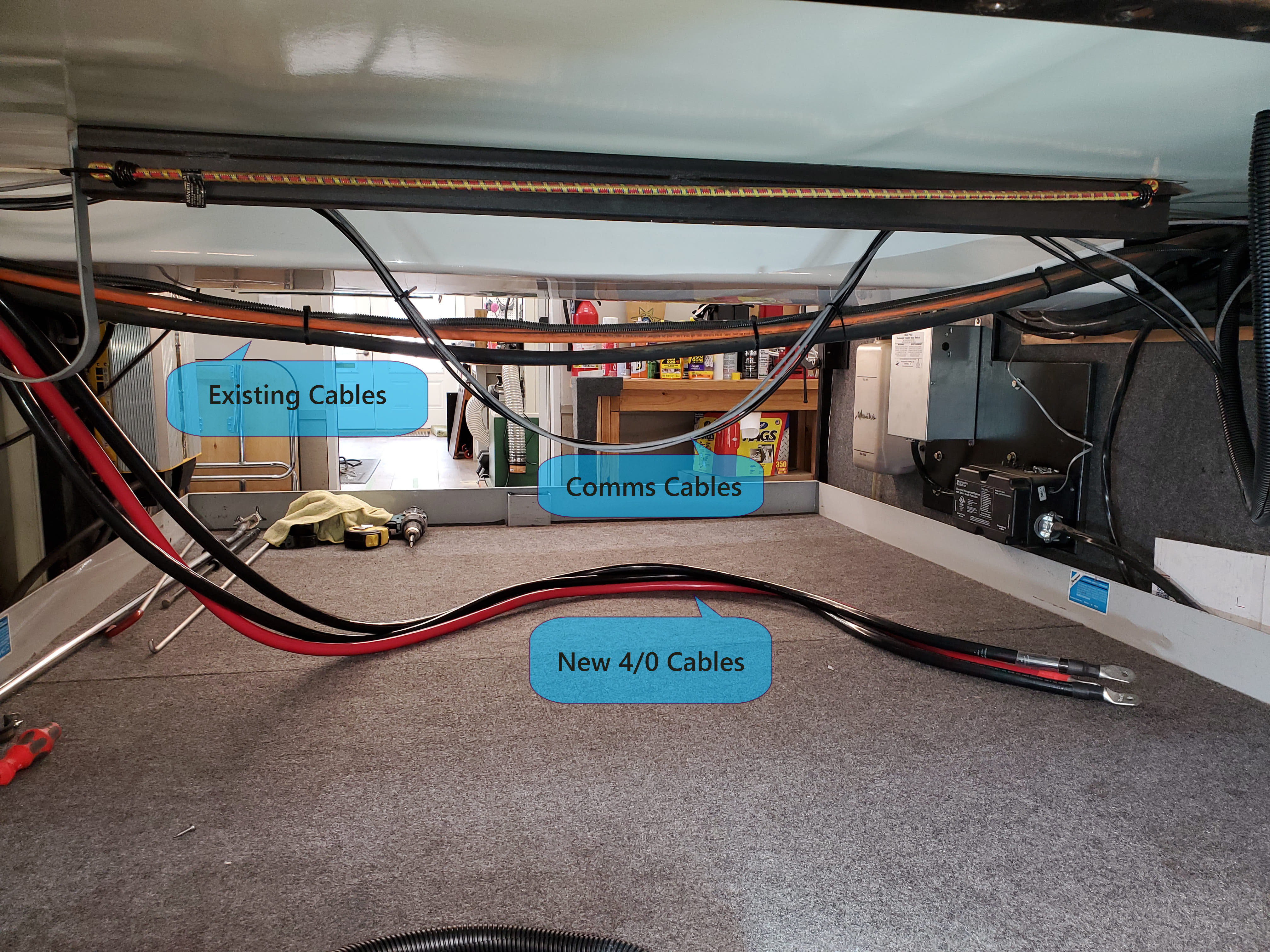
Three 4/0 cables — positive, negative, and ground — run from the Multiplus to the battery bay. Our coach includes a secondary, smaller raceway running along the bay ceiling parallel to the main one. It carries several DC lines (boost, ignition power, ground), and we found it had enough space to add our new cables, along with VE.Direct and VE.Bus communication lines.
The DC cables were terminated with correctly sized lugs and installed on the Multiplus. The ground lug needed a slight filing on the sides to fit through the case opening.
AC Wiring
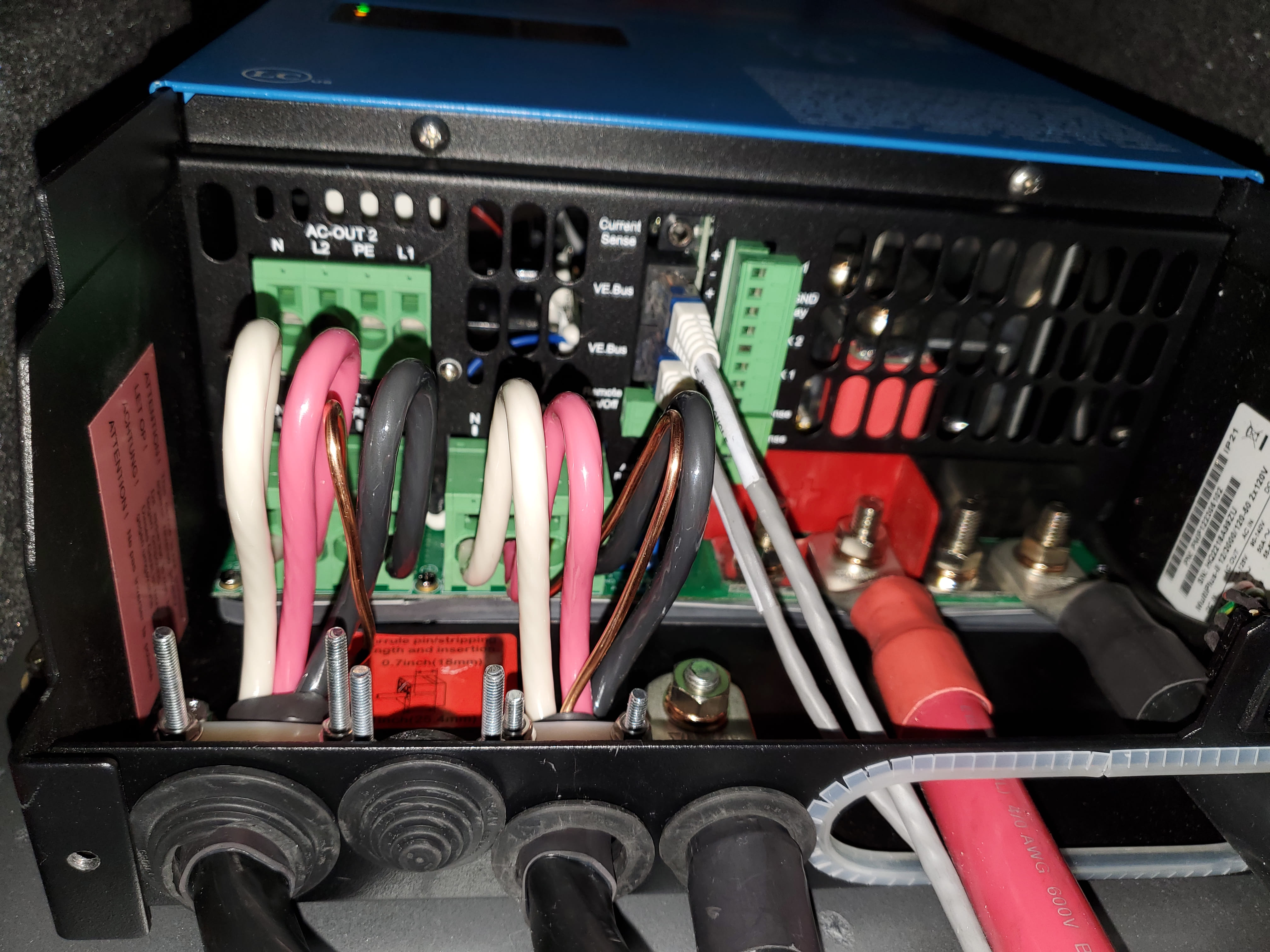
The AC wiring was straightforward, thanks to generous space for service loops in the access area. Strip the cable jackets according to the installation guide — it’s probably more than you’d expect. The terminals use spring clips: press a small screwdriver into the release slot, fully insert the #6 wire, then remove the screwdriver to secure it.
With the (2) two transfer switches and the EMS relocated, the compartment at the foot of the bed now offers ample space. It’s a nice not having those components nearby —they tended to generate some heat and emitted a faint humming noise, neither of which will be missed.
Up Next
With the AC and inverter side complete, its now time for the Battery and Solar portion of the install.