Preparing for a Victron Multiplus II
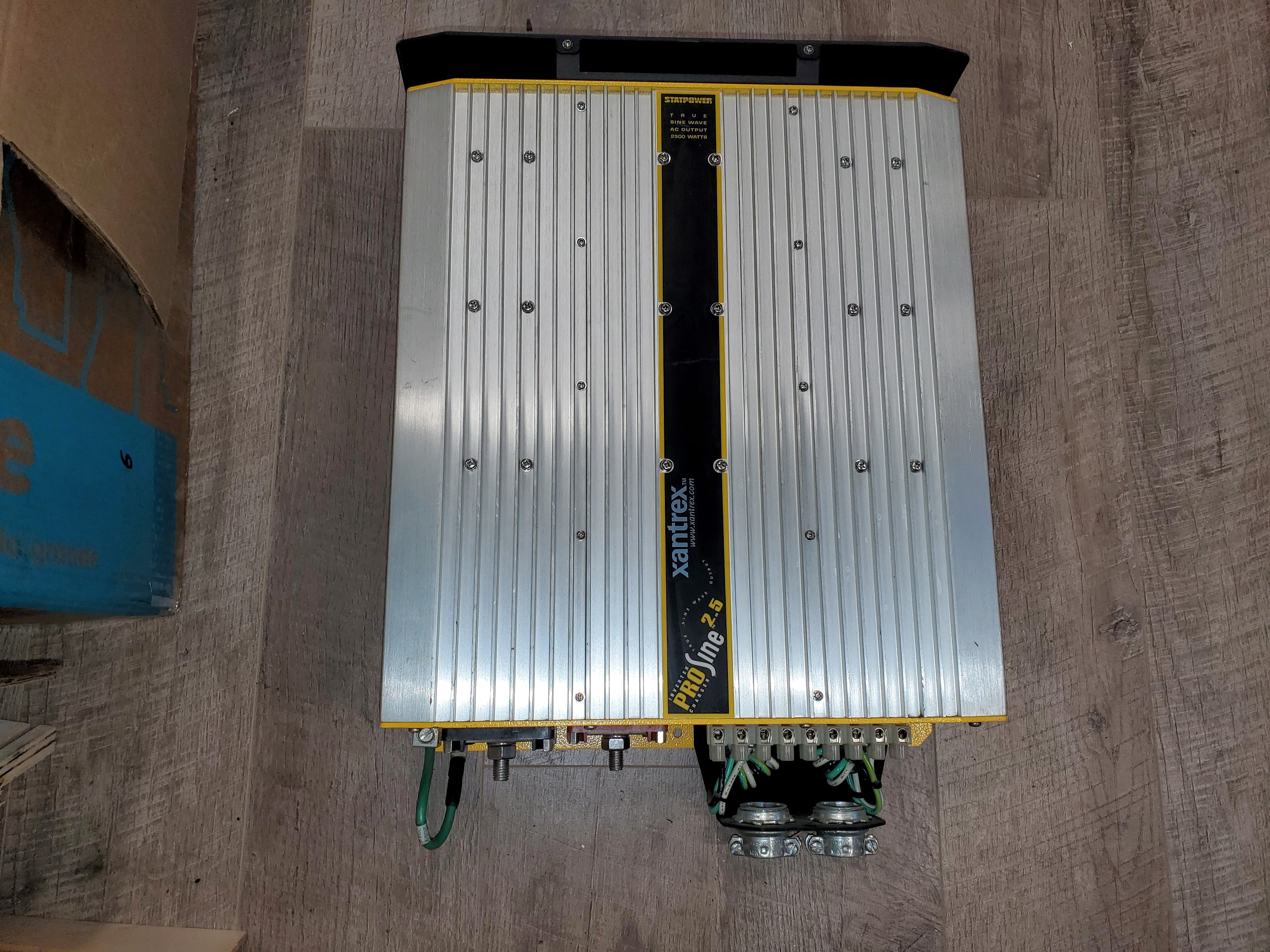
We wanted to replace our XanTrek ProSine 2.5 inverter/charger with something more modern. We also wanted to update the Heliotrope RV-30DE solar charge controller as well as replace the single 100Watt solar panel that we had. We ended up choosing a Victron based system as we liked the features as well as many system components they offer.
We’re not off-grid diehards or long-term boondockers, so our install is not going to be a solar panel, battery capacity, 48V, drool worthy juggernaut. Our focus was on functionality, quality, and integration. Step one: choose components, learn how they work and connect, then figure out where they’d actually fit.
First a BIG thank you to @T and M Long for sharing their Victron schematic. For me this was the Victron Rosetta Stone as it outlined various electrical connections, recommended sizing’s as well as the needed communication lines so components could integrate / function together. With that in hand, and a credit card with lots of room, we got to ordering the various parts.
Parts
Here is a run down of what we used / installed.
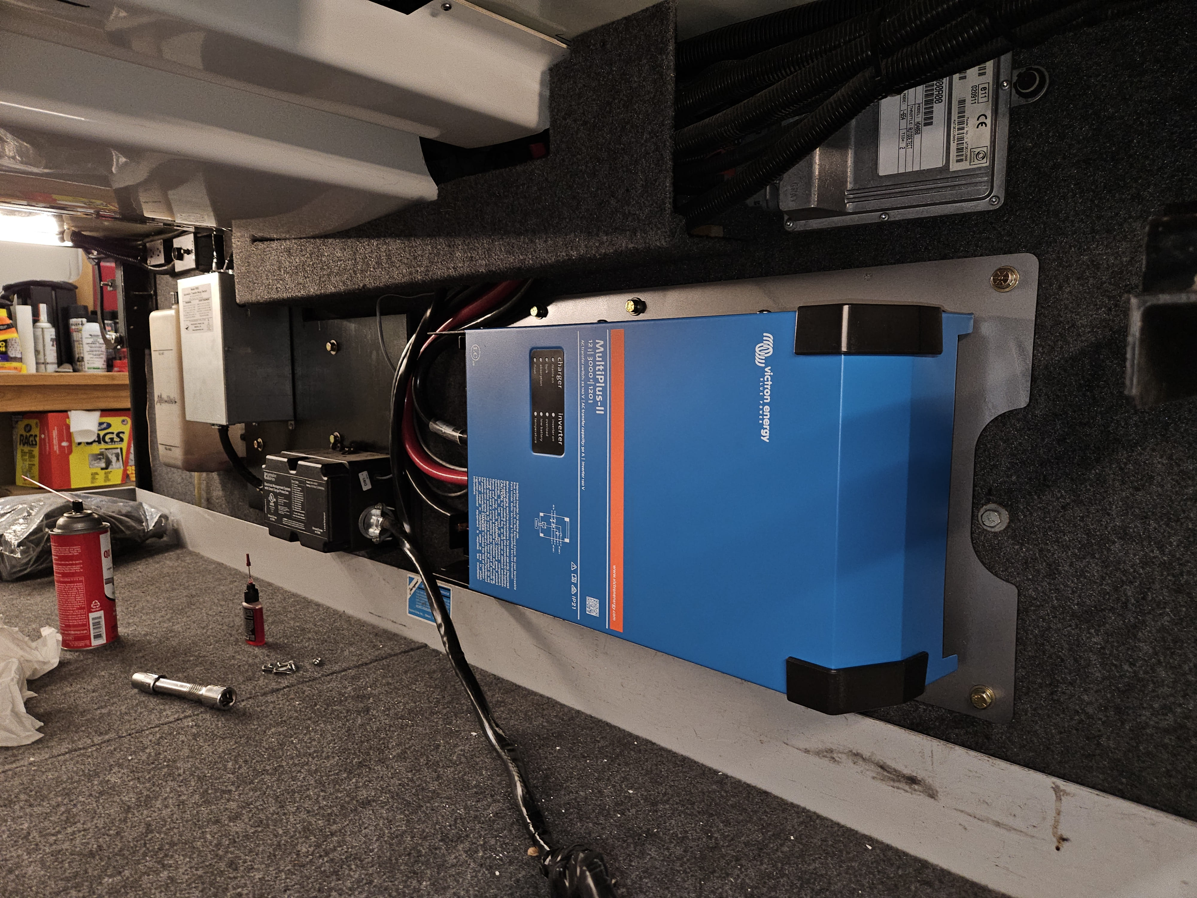
- Victron MultiPlus II 12/3000/120 50 2X120V
- Victron GX Touch 70 Flush
- Victron Orion XS 12/12 SOA DC/DC Battery Charger
- Victron Cerbo GX MK2 System Monitoring & Control
- Victron Lynx Distributor
- Victron SmartSolar MPPT 100V/50Amp/12/24V
- Victron Blue Smart IP22 Battery Charger 12V 30A
- Victron SmartShunt Battery Monitor
- Victron VE.Bus Smart Dongle
- Victron MK3 USBC (VE.Bus to USBC)
- Victron MEGA fuse (various sizes 400, 60)
- Victron VE.Direct cables (various lengths)
- Victron VE.Direct to USB Interface
- MidNite Solar BabyBox
- MidNite Solar (CBi OEM) 150vDC DIN Rail Breakers
- AM Solar C box V2 Rooftop Combiner
- MEGA 220 Watt Solar Panels
- Epoch 12V 460Ah Heated & Bluetooth LiFeP04 Essentials
- Disconnect Switch Pro Installer EZ Mount 400A
- Marine Grade Battery Cable (various AWG 4/0, 6)
- Marine Grade Duplex Flat Wire (10/2 and 6/2)
- Marine Grade Heat Shrink (various sizes)
- Lugs, Terminals, Connectors (various AWG & sizes M10/8/6)
Vendors
We used several vendors to get the best pricing we could. You have to shop around, look for sales, find coupons, check if they charge sales tax, shipping costs, etc. Here is the short list of where we purchased the majority of the above items for this project.
- RV Solar Connections (Victron, bulk cable, lugs, shrink tube)
- Bay Marine Supply (Victron, bulk cable, lugs, shrink tube)
- Rich Solar Panels (Solar Panels)
- Epoch Batteries (Batteries)
- Ferrules Direct (Various connectors)
- Battery Cables USA (Bulk cable / lugs)
- Amazon (Victron, various connectors, etc.)
- TemCo Industrical (Compression crimper, the bomb, the real deal)
How much??

Make it rain sums up the cost.
Layout
Figuring out where to place various components took some time. There are A BUNCH of inspiring installations on Foreforums, I looked at many of those to get ideas. Since we have a 36’ I tended to look for installs done in 34-36’ coaches. I also wanted to keep most of items out of the interior, again at 36’ giving up an closet was not really an option.
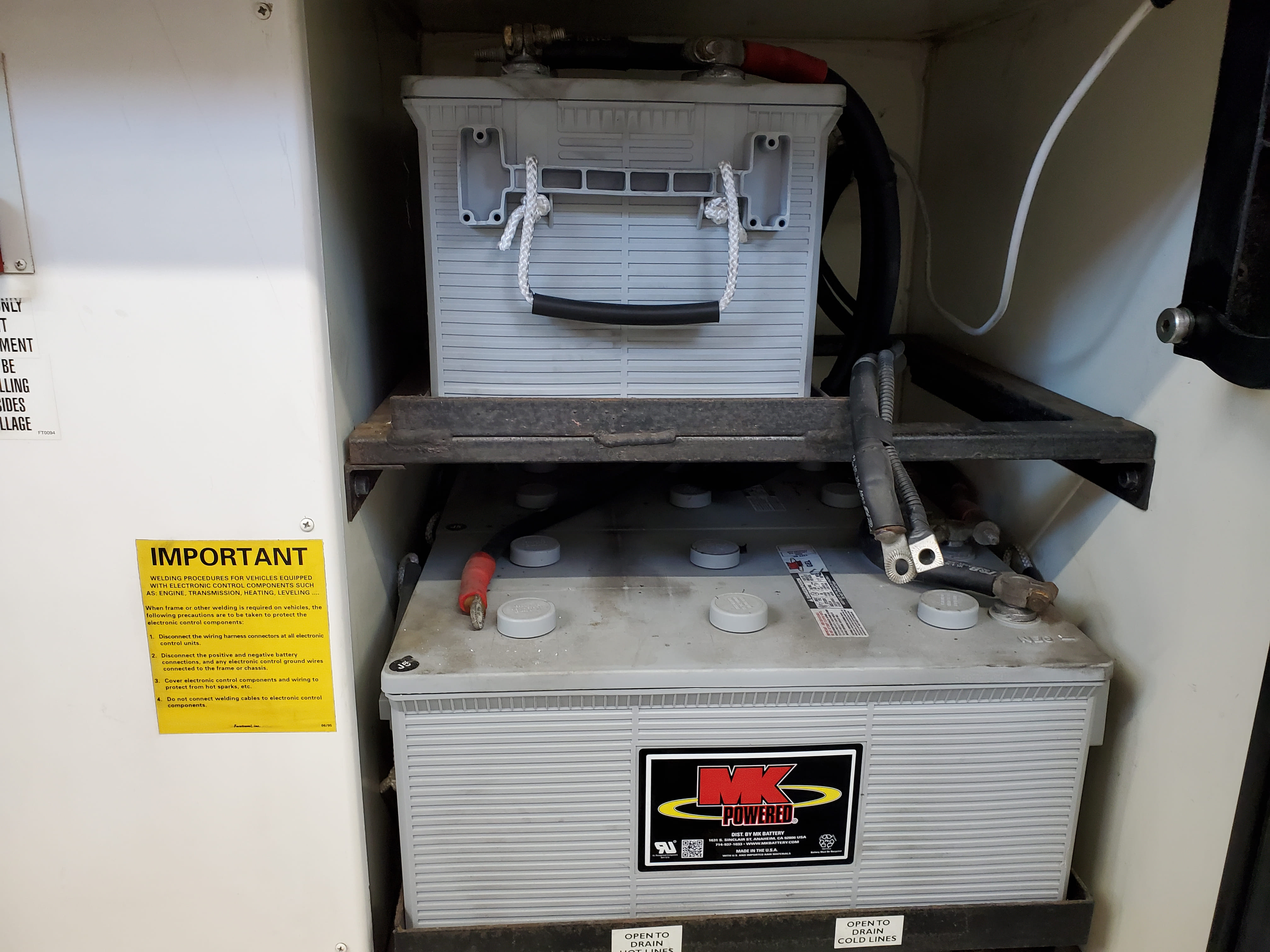
One install that I found interesting was by @floridarandy Victron Power Thread as it showed using the area above the house batteries. Another good area would be the propane bay if you have removed the tank (we have not .. yet)
The DC wiring to Multiplus was as straight forward as it could be. Change from the OEM 3/0 to 4/0 and routing it to new locations.
The AC wiring was going to be more involved. The existing layout has the Generator and Shoreline (both Romex 6/3G) running to the foot of the bed where the transfer switches, progressive EMS and circuit breaker panels are located. The existing ProSine has two AC lines running from the breaker panel, one 12/2G used as inverter power and one 10/2G used for inverter output. Neither of those is sized for the Multiplus II 2x120 which requires 6/3G in and out.
AC Wiring Options
There were two options to consider.
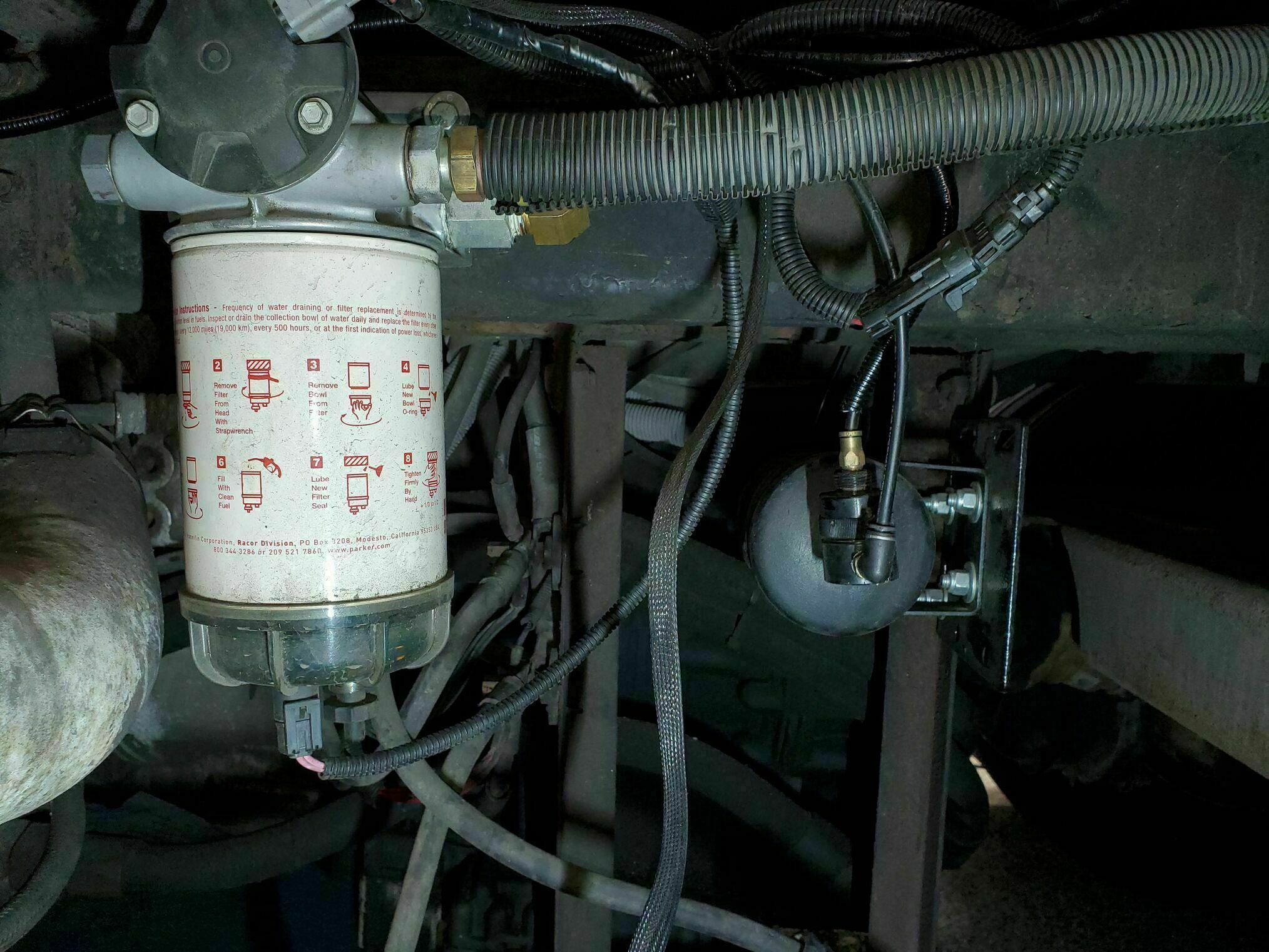
I came across several posts describing a common approach: running two 6/4 SOOW or SJOOW cables (think heavy-duty shore cord) from the inverter bay, through the rear bulkhead, along the chassis underbelly—above the transmission—and up into the compartment behind the bed. In that setup, one cable connects to the output of the shore/gen transfer switch, while the other feeds the main breaker. The area is already packed with factory wiring, hoses, and conduits, so there are plenty of existing supports and pathways to secure the new cables along the way.
Another way, and the way I chose:
 I cut the existing generator Romex 6/3G just before it transitioned from the utility bay (located above the waste tanks) into the space beneath the closet floor. The end of the cable coming from the generator was then pulled back into the inverter bay. It will now serve as the generator input to the transfer switch—performing the same function as before, just relocated to a new position.
 The other end of the cut Romex was used to pull and guide a new length of 6/3G from the inverter bay, through the closet floor, along the cable trough beneath the bedroom, and into the compartment at the foot of the bed. Essentially, I was just replacing the original line with a longer one that could reach the inverter.
This new run now serves as the inverter output, feeding the main breaker. I could have spliced into the existing cable to extend it, but I opted for a continuous run to avoid introducing unnecessary connections.
 I Moved the shore/generator transfer switch and progressive EMS to be next to the inverter, removing it from the foot of the bed. The second transfer switch is no longer needed and was removed, its function is handled by the Multiplus.
 The other Romex 6/3G, that ran from the shore line junction to the foot of the bed, was pulled back from the bedroom to the utility bay.
It was routed to the bay with the inverter and will be used as shore input to the transfer switch, the same function it had, just in a new location.
To improve access, we did remove the upper cable raceway and supported everything while we worked on the connections. This was also a great time to remove few mouse nests, stank and remains that were in the raceway (nasty stuff)
Notes & Summary
We now have a single 6/3G Romex running from the inverter bay to the foot of the bed. The original (2) two 6/3G lines, that had ran to the foot of the bed, now run to the relocated transfer switch. No lines are run outside the coach and all the AC lines are grouped together. The ProSine 12/2G & 10/2G lines were disconnected and remain in place for any future needs.
 You must remove the closet floor to access and loosen several cable clamps. You also have to loosen the silicone carne plug that seals the two (2) 6/3G cables where they penetrate the floor.
Cable lube is a help when the pulling of the cables through those areas. The cable pulling and moving did not take even an hour.
An assistant to help field questions like, “Can you see which line is moving?”,”Try pulling now… wait, not that one!”, “I’m stuck can you help me get out of here?”, “That stain/scratch must have been there already.”, “Did you take my 10mm socket?” is also a great help and adds to the fun.
Next post I’ll outline some of the bay wiring and mounting for the inverter